background image


U

U

s

s

e

e

r

r

'

'

s

s


M

M

a

a

n

n

u

u

a

a

l

l


RT-665D 


15” All in one POS PC 


(M/B: FH-5251) 


Version 1.7


Copyright © 2012. All rights reserved. 

All other brand names are registered trademarks of their respective owners. 


Summary of Contents for RT-665D

Page 1: ...1 U Us se er r s s M Ma an nu ua al l RT 665D 15 All in one POS PC M B FH 5251 Version 1 7 Copyright 2012 All rights reserved All other brand names are registered trademarks of their respective owners...

Page 2: ...ation provided in this manual is intended to be accurate and reliable However Firich Enterprise Co Ltd assumes no responsibility for its use nor for any infringements upon the rights of third parties...

Page 3: ...it Do not place anything over the power cord 10 All cautions and warnings on the equipment should be noted 11 If the equipment is not used for a long time disconnect it from the power source to avoid...

Page 4: ...on and Setup 16 Driver Download from FEC Website Model 16 Chipset Driver Installation 17 VGA Driver Installation 19 LAN Driver Installation 20 Audio Driver Installation 21 ELO Touch Tools Installation...

Page 5: ...Cash Drawer Port Is Not Functioning Properly 49 USB Device Is Not Functioning Properly 49...

Page 6: ...h quality oriented and cost effective concept Fanless as it is RT 665D provides a decent choice for noise free environment applications with optimized product reliability Main Features _ Fanless Solut...

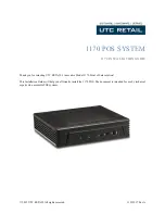
Page 7: ...A Quick Tour for RT 665D Before you start take a moment to become familiar with RT 665D...

Page 8: ...RT 665D Dimension...

Page 9: ...Rear I O Panel...

Page 10: ...s an additional serial port switching cable provided RJ11 connector Cash Drawer Connector 12 V actuation support PS2 connector Connect the keyboard or mouse to this port COM 2 D SUB 9 connector The se...

Page 11: ...he unit 3 Open the cover and pull out the HDD tray 4 Remove 4 screws to change HDD Fasten back 4 screws and put the tray back 5 Restore the maintenance cover to the system 6 Fix the cover with the scr...

Page 12: ...emove the power cord 2 Remove the cover in the back of unit 3 Fix the pole stand with screws with cover and lock them back with two screws 4 Connect the VGA and power cable to the system 5 Connect the...

Page 13: ...oor 3 Adjust the jumper setting 4 Restore the top cover 5 Connect the power cord to the system VFD Customer Display Installation 1 Turn off the power and remove the power cord 2 Remove the cover in th...

Page 14: ...Notepad etc first and then press Ctrl Alt F10 The following menu will appear accordingly For detailed instruction please refer to the MSR212 Programmer s Manual in FEC website Cash Drawer Installation...

Page 15: ...voltage of the solenoid is DC 12V I O port 284 is used for drawer operation A test program is supplied for Linux and Windows source code of which is available on request by software developers Value D...

Page 16: ...t ti io on n a an nd d S Se et tu up p Driver Download from FEC Website Model A Please go to FEC website and download the drivers B The installation sequence Chipset Driver VGA Driver LAN Driver Audio...

Page 17: ...uence accordingly Chipset Driver Installation Intel ATOM D525 Chipset Installation Utilities for Windows XP Step 1 Please download the Intel chipset driver from website Step 2 Click Next Step 3 Read t...

Page 18: ...4 Click Next and the drivers for the Intel Chip set will install Step 5 Please wait while the setup program processing Step 6 When the Setup COMPLETE message appears click Finish to restart your comp...

Page 19: ...lling the IEGD driver for VGA under POSready 2009 the default setting is 800x600 with Clone mode if you need to use Extension Mode please set the 2nd panel as primary as below Warning After you set th...

Page 20: ...system LAN Driver Installation Step 1 Please double confirm the LAN driver from website Step 2 Click Next to continue Step 3 Click Next to continue Step 4 Click Next to continue Step 5 Click Finish t...

Page 21: ...Audio Driver Installation Step 1 Please download the Audio driver from website Step 2 Click Next to continue Step 3 Click Next to continue...

Page 22: ...ck Finish and restart the system ELO Touch Tools Installation 1 Find the setup file through index Tools 2 Open SW601854_TETouch_5 4 2 exe for latest version please reference to FEC website 3 4 Click O...

Page 23: ...5 Click Unzip Unzip the files successfully and click OK to continue the installation 6 Click Next to continue 7 Choose Install Serial Touch Screen Driver and click Next to continue...

Page 24: ...greement and click Yes and select Auto Detect ELO touchscreens and click Next 9 Select COM3 and click Next for further installation steps 10 Setup complete and execute Calibrate Elo Touch Screen Monit...

Page 25: ...he targets showed on the screen 12 According to ELO Touch Screen Properties Confirm the Touch Driver Version is 5 2 0 43 and Make sure the COM port listed is COM3 for your touch monitor adjust a prope...

Page 26: ...START YOUR COMPUTER TO UTILIZE YOUR TOUCHSCREEN FEATURES 14 Click Restart to reboot your computer again ELO Control Panel This section explains the different options in the ELO control Panel General t...

Page 27: ...ttons tab allows you to Adjust all mouse emulation controls Change cursor properties Enable or disable right mouse button utility Sound tab The Sound tab allows you to To change sound properties for E...

Page 28: ...Properties tab The Diagnostics tab allows you to View Controller Information About tab The About tab displays Information about ELO Touch systems...

Page 29: ...EETI TouchKit Tools Installation Step 1 Please double confirm the EETI driver downloaded from website Step 2 Click OK to continue unzip the driver Step 3 Open Setup exe Step 4 Click Next...

Page 30: ...Step 5 Click Next Step 6 Click OK to close the pop up dialog Step 7 Click Support Multi Monitor System and then Next to continue Step 8 Click Next...

Page 31: ...Step 9 Click OK and turn off the computer to restart your system again After the system finish rebooting follow the directions to calibrate the Touch screen...

Page 32: ......

Page 33: ...ptions in the TouchKit control Panel General tab The general tab allows you to Manage the touch screen controller you installed Tools tab The tools tab allows you to Calibrate the touch screen with th...

Page 34: ...confirm the Wireless LAN driver from website Step 2 Click Next to continue Step 3 Select Install driver and Ralink WLAN Utility Step 4 Select Ralink Configuration Tool Select Optimize for WiFi mode St...

Page 35: ...RT 665D 35 Step 6 Select Finish to complete the installation...

Page 36: ...eaker Integrated 2W x 2 stereo system speakers Power 90 watts external power adaptor I O Port Serial Port 4 x User available COM ports COM1 COM4 and COM5 RJ45 COM2 DB9 Parallel Port 1 x Bidirectional...

Page 37: ...on A DC_IN DC Adapter 12V in B 12V_OUT 12V OUT C COM4_USB1 VFD RS 232 port USB 2 0 1 1 port The definition of pin1 pin 2 and pin4 are depending on jumper setting from JCOM4 and VFD_JR1 Pin Definition...

Page 38: ...AN1 Pin Definition 1 USB 5V 2 D 3 D 4 GND COM2 Pin Definition 1 DCD 2 RXD 3 TXD 4 DTR 5 GND 6 DSR 7 RTS 8 CTS 9 RI 5V 12V VGA Pin Definition 1 RED 2 GREEN 3 BLUE 4 NC 5 GND 6 GND 7 GND 8 GND 9 VCC 5V...

Page 39: ...State Description On Transmitting Off Not Transmitting Activity LED Pin Definition 1 Data 0 2 Data 0 3 Data 1 4 Data 1 5 Data 2 6 Data 2 7 Data 3 8 Data 3 LPT Pin Definition Pin Definition 1 STB 14 A...

Page 40: ...K Audio Line Out Pin Definition 1 Keyboard Data 2 Mouse Data 3 GND 4 Mouse Clock 5 5V 6 Keyboard Clock RJ11 Pin Definition 1 GND 2 GPIO 0 3 CASH Drawer Switch 4 12V 5 GPIO 1 6 GND Audio Jack Pin Defin...

Page 41: ...This connector is reserved for future use 2 CPU_FAN CPU FAN 3 SYS_FAN System FAN CPU_FAN Pin Definition 1 GND 2 12V RPM control 3 RPM detect 4 RPM control SYS_FAN Pin Definition 1 GND 2 12V RPM contro...

Page 42: ...Backlight 5V 3 EDID Data 14 Backlight Controller 25 GND 4 GND 15 Data1 26 GND 5 EDID Clock 16 GND 27 Data2 6 NC 17 Data1 28 LVDS Power 3 3V 7 GND 18 GND 29 Data2 8 NC 19 GND 30 LVDS Power 3 3V 9 Data...

Page 43: ...r 12V customer display JCOM3 is pre set as 1 2 short for 5V Touch controller Default 1 2 Pin Definition 1 RS232 2 UART RXD 3 RS422 4 UART RXD 5 RS485 6 UART RXD JRS2 Default 2 3 short Pin Definition 1...

Page 44: ...Pin Definition 1 CTS4 2 RTS4 3 Signal for PIN2 of COM4 port 4 Signal for PIN4 of COM4 port 5 RI4 1_5V 12V_F 6 GND PS JCOM4 is set to 5 6 short for 12V VFD display as default VFD Mode VFD_JR1 1 2 3 5 4...

Page 45: ...ion LED 6 Stand by 5V 7 HDD LED 8 VCC 5V 9 System Reset 10 GND 13 F_USB1 F_USB2 USB Pin header Pin Definition Pin Definition 1 USB Power 5V 2 USB Power 5V 3 USB Dx 4 USB Dy 5 USB Dx 6 USB Dy 7 GND 8 G...

Page 46: ..._AUDIO Front Audio Box header Pin Definition Pin Definition 1 Amplifier Out_R 2 MIC_L 3 Amplifier Out_R 4 MIC_R 5 GND 6 Line In_R 7 Amplifier Out_L 8 Line In_L 9 Amplifier Out_L 10 Line In_JD 11 GND 1...

Page 47: ...D 2 Battery 3V 3 Battery 3V 18 SATAPW_1 SATAPW_2 SATA HDD Power 5V 12V Pin Definition 1 12V 2 GND 3 GND 4 5V 19 LCDPWR_CON LCD Power ON OFF 20 BKLTEN_CON Back light Inverter Enable Disable Default 1 2...

Page 48: ...h screen has been properly connected to the ELO controller or the TouchKit controller Attention Pin1 mark should be on the same side as the ELO controller E Check if the ELO controller Green LED is bl...

Page 49: ...COM5 Are Not Functioning Properly A Check if the I O ports are enabled in the CMOS setup B Check if there are any IRQ conflicts C The main board or I O cable could be defective Cash Drawer Port Is No...

Reviews: