background image

MBH6 MR1108 Rev. A

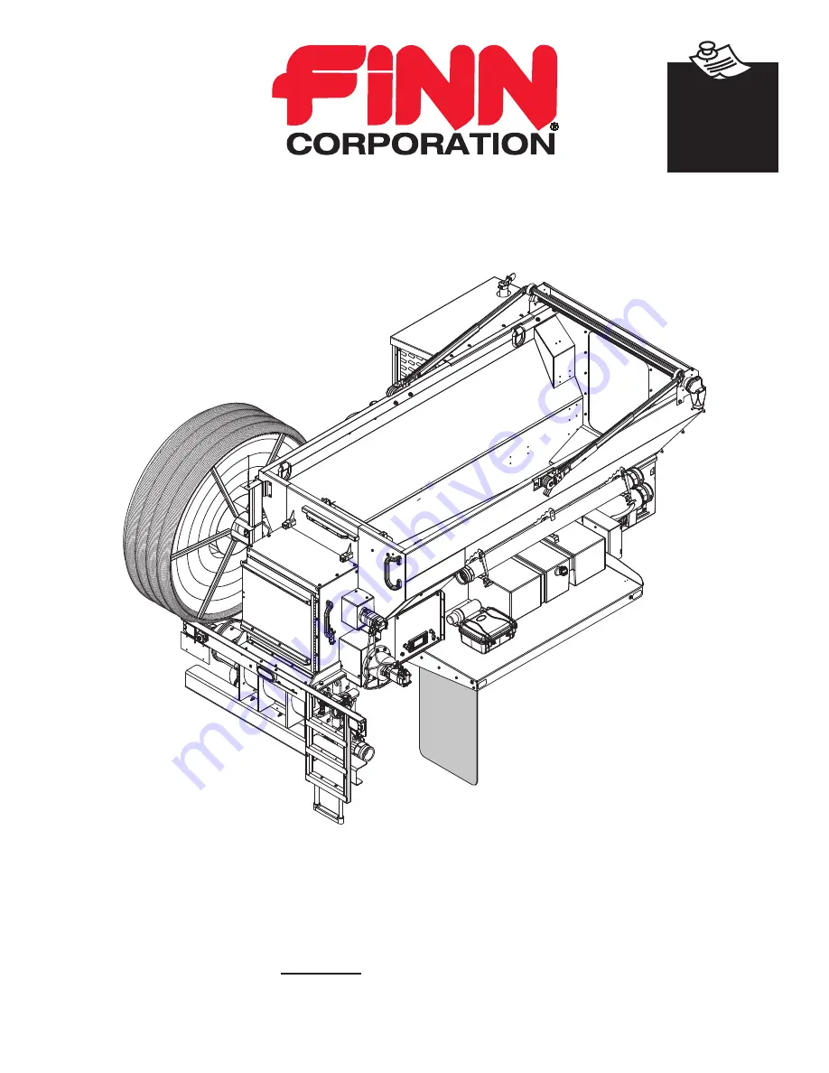
MBH6 Material Blower

Operator Instructions and Parts Manual

Item  

A2548-001

      Serial No.  _____________

9281 LeSaint Drive • Fairfield, Ohio 45014

Phone (513) 874-2818 • Fax (513) 874-2914

Sales: 1-800-543-7166

Activate

Activate

Your Warranty

Your Warranty

By Registering

By Registering

TODAY!!!

TODAY!!!

Summary of Contents for A2548-001

Page 1: ...structions and Parts Manual Item A2548 001 Serial No _____________ 9281 LeSaint Drive Fairfield Ohio 45014 Phone 513 874 2818 Fax 513 874 2914 Sales 1 800 543 7166 Activate Activate Your Warranty Your Warranty By Registering By Registering TODAY TODAY ...

Page 2: ...FOR OFFICE USE ONLY DATE UPDATE DESCRIPTION CODE 08 30 19 Initial release MR0830 11 08 19 Revision A Part number corrections and hose reel update MR1108 ...

Page 3: ...tigation 6 Labor hours must coincide with the published Labor Schedule or estimate approved by the Finn Warranty Administrator 7 Once work is done a Finn Warranty Claim Form must be filled out and emailed along with any related receipts or invoices to the Warranty Administrator We ask that this is done ASAP after work is completed Faulty or failed parts IF Finn wants you to return failed parts you...

Page 4: ......

Page 5: ...tions Screen 32 60 Dust Suppression 33 Settings 34 36 Floor Settings 37 USB 38 Hose Reel Settings 39 Diagnostics 40 45 Radio Remote Diagnostics 46 49 Language 50 About 51 Regeneration 52 60 Crew Members and their Duties 61 The Material Feed System 61 65 Material Handling Group 61 Hydraulic System 62 Description of Valve Systems 62 63 A Airlock 62 B Floor Drag Conveyor Feed Roll 63 C Hose Reel 63 H...

Page 6: ...l 81 127 MBH6 Truckmount Assembly 82 83 Engine 84 85 Air Intake and Exhaust System 86 87 Engine to Blower Coupling 88 89 Radiator Assembly 90 91 Airlock Assembly 92 93 Blower and Air Piping System 94 95 Feed Roll Assembly 96 97 Floor Assembly 98 99 Canopy Assembly 100 101 Metering Door Assembly 102 103 Dust Suppression System 104 105 Tarp Assembly 106 107 Hydraulic Manifold 108 109 Hydraulics Syst...

Page 7: ...n which if not avoided WILL result in death or serious injury Warning indicates a potentially hazardous situation which if not avoided COULD result in death or serious injury Caution indicates a potentially hazardous situation which if not avoided MAY result in minor or moderate injury Notice indicates important information that if not followed MAY cause damage to equipment NOTE This is helpful in...

Page 8: ...f hose is cracked bulging or damaged replace immediately 5 Inspect the material discharge hose and connections for cracks or damage If cracks or damage are found replace affected part immediately II MACHINE OPERATION 1 Always wear safety goggles when operating and or feeding the machine Other safety attire such as safety shoes ear protection gloves hard hats dust masks etc should be worn as requir...

Page 9: ... Deadly carbon monoxide fumes can accumulate 9 Never operate this or any other machinery when fatigued tired under the influence of alcohol illegal drugs or medication You must be in good physical condition and mentally alert to operate this machine 10 Never modify the machine Never remove any part of the machine except for service and then reinstall before operating 11 During application through ...

Page 10: ...cts water into sensitive electrical components To clean the unit use a method that controls the amount of water that is applied to the surface of the unit III MAINTENANCE 1 Before servicing the machine turn off engine and allow all moving parts to stop To prevent accidental starting disconnect battery cables Tag the engine operating area to show that the machine is being serviced Use lockout tagou...

Page 11: ...azard Electrostatic Sensitive Area Hazard Pinch Point Entanglement Hazard Carbon Dioxide Hazard Explosive or High Pressure Hazard Grounding Required Hazard Corrosive Hazard Explosive Material Hazard Crush Hazard Cut Crush Hazard Vision Damage Hazard Crush Pinch point Hazard Cut Sever Hazard Vision and Hearing Damage Hazard Crush Entrapment Hazard Sever Reach Hazard Vision Hearing and Respiratory D...

Page 12: ...equired Pinch Point Moving Belt Hazard Trip Hazard Breathing Vision Hearing and Head Protection Required Poison Hazard Watch Head Overhead Hazard Foot Protection Required Radio Frequency Hazard Fall Loss of Balance Hazard Lockout Tagout Procedure Required Remote Start Hazard Mandatory Operator Action Required Gloves Required Sever by Rotating Parts Hazard Read Manual Trailer Safety Rotating Shaft ...

Page 13: ...7 Do Not Ride on Moving Vehicle Do Not Remove Guards Do Not Obstruct or Block Do Not Spray Power Lines Do Not Touch Do Not Pressure Wash COMMON SAFETY SYMBOLS SAFETY DECAL EXAMPLES ...

Page 14: ...n it contains illustrations and a complete list of parts and components for easy identification HOW THE MATERIAL BLOWER WORKS The bulk material is loaded into the hopper by a loader or by a feed elevator Located at the bottom of the hopper is a drag chain conveyor that conveys the bulk material to an opening in the rear of the hopper containing a feed roll The feed roll and drag chain conveyor fee...

Page 15: ...e blower must be securely mounted onto it The FINN Material Blower should be mounted by a qualified truck body installer Failure to comply could result in personal injury Failure to comply could also result in product or property damage Install Mount the FINN Material Blower in compliance with the vehicle ratings machine mounting requirements and applicable laws Failure to do so could result in pe...

Page 16: ...NTING LOADING INFORMATION MINIMUM CLEARANCE FROM BACK OF CAB MINIMUM CLEARANCE FROM BACK OF CAB 149 98 C L CHASSIS 126 11 MIN 27 47 6 6 108 TRUCK RAIL MOUNT CLEARANCE ZONES 15 5 22 5 31 5 CG Y CG X FRONT REAR CG Z ...

Page 17: ...CG Y CG Z WEIGHT MBH6 No Material 82 5 in 9 in 18 75 in 7 169 lbs MBH6 Full 6 yard 74 in 3 in 26 in 12 275 lbs Maximum Capacity Rating 5 106 lbs Assumes six 6 yards of mulch weighing 851 lbs cu yd NOTE All dimensions are in inches drawings are not to scale MUD FLAPS ...

Page 18: ... 0 37 in 9 4mm GAP ITEMS PRE INSTALLED AT FACTORY MATCH THROUGH HOLES DRILL 11 16 in 17 5mm THROUGH BOLT 3X BOTH SIDES ZINC PLATED HARDWARE M16 x 2 CLASS 10 9 or 5 8 11 UNC GRD 8 OR EQUAL TORQUE TO 212 ft lb 287 N m DO NOT WELD TO CHASSIS TOP OF FRAME RAIL 2 50 in 63 5mm FRONT SPRING MOUNT ...

Page 19: ...TALLED AT FACTORY HOPPER BODY TRUCK CHASSIS FRAME RAILS ZINC PLATED HARDWARE M16 x 2 CLASS 10 9 or 5 8 11 UNC GRD 8 OR EQUAL TORQUE TO 212 ft lb 287 N m DO NOT WELD TO CHASSIS TOP OF FRAME RAIL 3 75 in 95 3mm MATCH THROUGH HOLES DRILL 11 16 in 17 5mm THROUGH BOLT 4X BOTH SIDES REAR FIXED MOUNT ...

Page 20: ...IDE SHIFT MOUNTS OPTIONAL LOCATION FOR SIDE SHIFT MOUNTS TRUCK MOUNTING LOADING INFORMATION CONTINUED The front spring mounts must be configured as shown below in located in 1 of the 3 options shown below The single side shift mount must be located in one of the available two open slots ...

Page 21: ...UNF 3 4 16 in Grade 8 6 2 011563 Truck Mount Compression Spring 4 3 A3453 001 Spring Spacer Tube 4 4 A3450 001 Truck Mount Gusset 2 5 A3448 001 Square Washer 8 6 Wide Plain Washer 3 4 in 12 7 Hex Bolt 3 4 16 in UNF x 7 in Grade 8 4 8 A3462 001 Truck Mount Gusset 2 9 Hex Bolt 3 4 16 in UNF x 3 in Grade 8 2 10 A3547 001 Upper Gusset Mount 2 11 A3549 001 Rear Hard Mount 2 KITS AND MARKERS A4511 001 C...

Page 22: ...h at a higher rate because it is easier to cut There are many different types of material that can be successfully processed through your Material Blower These materials are categorized into three main groups These classifications are important when considering machine performance material feed rate and overall operation 1 Dry Aged Material Aged double and triple processed bark mulch saw dust or w...

Page 23: ...foreign objects that could injure workers or damage equipment when the machine is started 9 Ensure that tarp is open and secured in place Never operate machine with tarp covering hopper Allowing the tarp to hang or sag over hopper during operation raises the risk that the tarp will be pulled into the equipment This will cause damage to the unit and could be a risk to the safety of the operator 10 ...

Page 24: ...18 Key Engine Start Emergency Stop e stop Digital Display Control Panel Tarp Control Switch USB Port Main Control Panel CONTROL GUIDE ...

Page 25: ... machine Tarp Control Switch A toggle switch used to open and close the tarp on the unit Make sure the tarp or tarp arms will not come into contact with anything above it before using the tarp control switch USB Port An access point for system and software updates Key Engine Start Ignition switch which turns on the unit for operation It has three settings an OFF position a RUN position which will ...

Page 26: ... Stop Toggle Switch Run Blower On Off Increase Decrease Material Feed Rate Increase Decrease Blower Speed Toggle Switch Material Feed Floor On Off Indicates Battery Life and Remote Connection Power Button Remote Connection and Control No Function 0 100 0 100 Radio Remote Transmitter CONTROL GUIDE CONTINUED ...

Page 27: ... setting MINUS Button Used to decrease a setting CONFIGURATION Button Switches the screen to the other options screens FUEL LEVEL Icon This meter indicate the fuel level in the unit it does not indicate the fuel level of the truck the unit is attached LEFT ARROW Button Used to go up to the next or previous screen option RIGHT ARROW Button Used to go up to the next or previous screen option BACK Bu...

Page 28: ... and or additional cooling may be recommended Consult the factory or local representative for appropriate information BLOWER COMPONENT INFORMATION This blower system is a rotary lobe blower providing positive displacement The pumping capacity is determined by size operating speed and differential pressure conditions Blowers employ rotors rotating in opposite directions within a housing closed at t...

Page 29: ...er check the oil sumps as described in the Blower Component Filling Procedure Add oil to the blower in the capacity quantity listed in the table Make sure oil level is maintained within the notched area of the sight glass Lower drive blowers have bull s eye type oil level gauges Maintain oil levels at the center of the glass Never attempt to change or add lubrication while the Material Blower is r...

Page 30: ... the fill plugs or breathers from both gear end and drive end plates 2 Slowly pour oil through the fill until oil appears in the oil sight glass Bring the oil level to the center of the sight glass 3 Verify oil level is at proper level in both gear end and drive end sight glasses 4 Replace the fill plugs or breathers that were removed in step 1 ...

Page 31: ...osition and wait for control pad to illuminate and go through its start up procedure MENU NAVIGATION The eight system softkeys are used to navigate between displays select menu items and change data Pressing any of the navigation softkeys will display the softkey menu that is associated with each softkey Your unit should display the normal Home Engine Off screen at the beginning but should the scr...

Page 32: ... The display will still indicate that the radio remote is still turned off At this point the controller is awaiting a decision from the operator on whether or not the radio remote will be used during operation If machine interlock errors are present for the unit they will appear after the controller is ONLINE The screen shown here illustrates that there are multiple Emergency Stop E Stop buttons t...

Page 33: ...INUED RUNNING UNIT WITHOUT RADIO REMOTE With the Fault Code s cleared and door s closed the decision to run the unit without the radio remote is now an option Press the DISABLE RADIO softkey at this time and the screen will change to the screen shown ...

Page 34: ...cting this softkey now before the engine is started will eliminate searching through the sub menus after the engine is started NOTE The HR FREE WHEEL option is limited on time If the option is not selected within the time set see HOSE REEL SETTINGS the option will not be available on this screen and the hose reel will latch With the hose reel released attach the material hose to the discharge port...

Page 35: ...n the display and the unit is now ready for operational commands Pressing the BLOWER softkey or the FLOOR softkey on the control panel will put the system in LOCAL MODE At this point FLOOR and BLOWER commands from the control panel will be accepted and the radio remote will be locked out from control To use the radio remote both the floor and the blower will need to be turned off Refer to the Runn...

Page 36: ... open door s on the unit At this point in the initial startup the decision to run the unit with the radio remote is an option Turn the radio remote on Turn the ignition key clockwise to the START position The key will return to RUN position during operation once released This screen will appear on the display Press the power button again on radio remote to enable radio remote functionality ...

Page 37: ...he radio remote to put the system in RADIO MODE At this point RUN BLOWER and MATERIAL FEED FLOOR commands from the radio remote will be accepted and FLOOR and BLOWER commands from the control panel will be locked out To return to control panel use both the floor and the blower will need to be turned off and the radio remote will need to be powered off MATERIAL FLOOR STOP Toggle Switch Run Blower O...

Page 38: ...until softkey is released The Material indicator light on the handheld radio remote flashes green during Auto Rev Mode If the HR FREE WHEEL softkey has not been selected BEFORE starting the unit the operator can select the HR FREE WHEEL softkey to unlock the hose reel at this screen On this screen is an arrow symbol pointing to the right This softkey will take the operator to additional options fo...

Page 39: ... FLOOR softkey or the BLOWER softkey on the control panel Make sure all E Stops are released before attempting to activate the Dust Suppression System The Dust Suppression System will not activate if any of the E Stops on the unit are activated The Dust Suppression System will activate when the floor is moving forward A water icon will appear on the home screen when the Dust Suppression System is ...

Page 40: ...options The screen shown here is another set of options available on the unit To enter the settings of the Material Blower press the SETTINGS softkey Pressing the SETTINGS softkey will open up this screen The Material Blower is set for Imperial units of measurement by default but pressing the UNITS softkey will switch the unit to metric measurements ...

Page 41: ...r The blower settings screen allows the operator to adjust the blower turn off delay The delay is factory set for five 5 seconds Using the plus increase and minus decrease softkeys the delay can be adjusted to the length of time desired If the operator would like to return the blower turn off delay to factory settings press and hold the RESET softkey shown on this screen for three 3 seconds The tu...

Page 42: ...tkey to enter the passcode screen Enter the passcode to continue further in this options screen The number inside the box is the current number you are working with Use the left and right arrow softkeys to move left and right Use the plus increase and minus decrease softkeys to change the number Once the code is entered press the OK softkey To leave this screen press the BACK softkey ...

Page 43: ...t on the performance of the Material Blower The floor settings screen is shown here Use the up and down arrow softkeys to highlight the setting the operator wants to adjust Use the plus increase and minus decrease softkeys to change the setting Once changed press the SAVE AND BACK softkey to save the setting and return to the previous screen To return the floor settings to factory settings press a...

Page 44: ...e Material Blower to the USB stick If information is needed from a USB stick press and hold the RETRIEVE FROM USB softkey for three 3 seconds This will apply setting values from the USB stick to the various settings saved inside the display Yellow text will appear on this screen after each softkey press to inform the operator on status of the copy or retrieval Typical messages are as follows copy ...

Page 45: ...the Material Blower The hose reel freewheel button on the display will automatically latch off after a certain amount of time has passed per a passcode protected setting This setting s default value is five 5 minutes and adjustable from one 1 minute minimum to twenty 20 minutes maximum at one 1 minute increments Use the plus increase and minus decrease softkeys to change the setting The freewheel ...

Page 46: ... screen shown here there are other options available Pressing the DIAG softkey takes the operator to the DIAGNOSTICS screen The Diagnostics screen is shown here The options include viewing engine information listing FINN codes fault codes and further controls of the radio remote Pressing the ENGINE softkey takes the operator to the Engine Diagnostics screen ...

Page 47: ...ation that can assist in determining if there is an error in the engine or in a component of the engine Pressing the ENGINE CODES softkey will take the operator into one of two screens The first screen is a no active codes screen The left and right softkeys can be pressed to see if any other codes exist but seeing this screen informs the operator that there are no faults with the engine ...

Page 48: ...CONTINUED If there is more information or other codes past the first screen the left and right arrow icons will flash blue and red This screen shows that there is an engine code that needs to be addressed There is also another code to view since the right arrow icon is flashing red ...

Page 49: ...IONS SCREEN DIAGNOSTICS CONTINUED The Engine Diagnostics screen shown here provides the operator with access to the engine data This screen appears when the ENGINE DATA softkey is pressed More engine information is available when the arrow softkey is pressed ...

Page 50: ...tive code a screen similar to the one shown here will appear IF there are additional codes to view the direction arrows at the top of the screen will flash red and blue View the additional codes by pressing the arrow softkeys If there are no active Finn Codes the screen should appear similar to the screen shown here Also if the code situations are corrected the screen should look like this one onc...

Page 51: ...heck the normally closed contact block wiring to the e stops door switch and safety relay 4 Panel e stop normally open circuit shorted to another circuit Check wiring to the normally open contact block on the panel e stop 8 Controller is offline Check the power ground CAN High CAN Low wiring to the controller 9 Engine ECU is offline Check the power ground CAN High CAN Low wiring to the engine ECU ...

Page 52: ...s screen To do this test the radio remote should be fully charged the power on the remote should be ON and the remote should be linked to the unit See the RUNNING UNIT WITH RADIO REMOTE section to activate and link the remote This is the radio remote diagnostics screen Press RADIO TEST to begin a diagnostics test of the remote to ensure all switches and buttons on the remote are functioning correc...

Page 53: ...at the beginning of the test Move each switch up and down or press each button on the radio remote to send a signal from the remote to the unit If the unit received each signal correctly to match each function the screen shown here should be the final result Press the BACK softkey to return to the radio remote diagnostics screen ...

Page 54: ...F SIGNAL TEST softkey on the control panel will flash the STOP indicator light blue on the radio handheld at a constant rate If rate becomes less consistent the RF signal quality is dropping Use this feature to test RF signal quality when working in an environment that may be prone to RF signal interference This feature can be used to help prevent engine shutdowns due to loss of RF signal ...

Page 55: ...NOSTICS CONTINUED Return to the radio remote diagnostics screen Press DISABLE RADIO softkey Pressing DISABLE RADIO softkey on the control panel will hide the RADIO TEST and RF SIGNAL TEST softkey options The unit will no longer take commands from the radio remote until the unit is reset ...

Page 56: ...own here The screen displays the current language setting in yellow text next to the LANGUAGE softkey As shown here the current language setting is for English Pressing the LANGUAGE softkey switches the displayed language from English to Spanish Press the LANGUAGE softkey again to return the display to English ...

Page 57: ...s screen shown here Press the ABOUT softkey to view more information about the digital interface system Shown here the ABOUT screen shows system information The RESET HOURS softkey option will set the resettable hours value to zero this is an hour counter for end user use and not engine run hours ...

Page 58: ...ssure in the SF inlet outlet in the DPF rises the differential pressure sensor installed on the DPF detects the increase The Engine Control Unit ECU commands the intake throttle to adjust the amount of engine intake air to increase exhaust temperature to a sufficient level such that PM is combusted and eliminated Reset Regeneration Regeneration with the combined use of Assisted Regeneration and po...

Page 59: ...eration a notification and regeneration icon will display at the bottom of the screen NOTE The ECU will not perform Reset Regeneration within the first 50 hours of engine life NOTE The machine can be operated normally during Reset Regeneration The machine can also be turned OFF If this occurs Reset Regeneration will resume again when the machine has been turned back ON and the DOC temperature has ...

Page 60: ...not malfunctions The engine sound may change during idling operation at no load White smoke may be discharged from the exhaust pipe right after starting a cold engine or during acceleration This is due to the discharge of water vapor When the exhaust temperature increases the white smoke disappears The exhaust gas is purified through the catalyst installed in the DPF so the smell of the exhaust ga...

Page 61: ...mode with one display showing the regeneration inhibit icon and the regeneration request continuously displayed at the bottom of the screen Further the Auto Regeneration request message will re display every 30 minutes The machine can continue to operate with Reset Regeneration inhibited for 3 hours however after 3 hours a Stationary Regeneration request may occur RESET REGENERATION STANDBY DUE TO...

Page 62: ...d the operator will be alerted via the control panel that a Stationary Regeneration is required via a Diagnostic Trouble Code DTC even if Regeneration on the control panel is set to Inhibit The operator should immediately conduct the Stationary Regeneration by performing the following operation 1 Move the machine to a well ventilated and safe location 2 Press REGEN softkey 3 Press the HYDRAULIC IN...

Page 63: ...ttom of the screen Note When the Stationary Regeneration starts the engine speed increases gradually to high idle speed then the regeneration begins and may modulate engine speed throughout the process Note If Stationary Regeneration needs to be interrupted for any reason turn off the key switch Once the machine is restarted the Stationary Regeneration request will be repeated Once Stationary Rege...

Page 64: ... has the option of performing a Manual Stationary Regeneration should work conditions schedule require Manual Stationary Regeneration can only be completed after the engine has accumulated 50 hours or more since its last regeneration 1 Move the machine to a well ventilated and safe location 2 Press REGEN softkey 3 Press the HYDRAULIC INTERLOCK softkey ...

Page 65: ...will begin 5 At this point the ECU will take over control of the engine to perform the Stationary Regeneration and a notification of Stationary Active and the regeneration icon will be display along with a status bar 0 to 35 minutes at the bottom of the screen Note When the Stationary Regeneration starts the engine speed increases gradually to high idle speed then the regeneration begins and may m...

Page 66: ...Regeneration by performing the following operation 1 Move the machine to a well ventilated and safe location 2 Press REGEN softkey 3 Press the HYDRAULIC INTERLOCK softkey 4 Press the MANUAL REGEN softkey Note Stationary Regeneration will not begin if any of the following conditions are present Coolant temperature is less than 60 C 140 F The engine has not been running for 15 minutes An important D...

Page 67: ...m air pressure to 12 psi 82 7 kPa an inlet and outlet silencer for noise attenuation and an inlet air filter The drag chain conveyor receives material from the hopper and conveys it to an opening located at the rear of the hopper where the feed roll is located The feed roll ensures a uniform feed of bulk material to the airlock The feed roll is powered by a variable speed hydraulic motor The drag ...

Page 68: ...ltration NOTE The Finn Vulhydra hydraulic oil may be substituted for either of the two ISO oils listed below Please use the temperature chart to determine what oil works best in your situation DESCRIPTION OF VALVE SECTIONS The illustration shows the valve block and different hydraulic circuits Each circuit is controlled by two valves with the exception of the hose reel middle circuit The floor and...

Page 69: ...il flow to the floor and feed roll There is a pressure switch on the forward circuit that is set for 1 500 psi 10 342 kPa that triggers the auto reverse function on the floor C HOSE REEL The middle section of the manifold controls the hose reel The flow rate is factory set so that the hose reel winds at a rate of about 12 RPM 6 CONNECT TO FLOOR MOTOR NON DRIVE SIDE 6 CONNECT TO FLOOR MOTOR DRIVE S...

Page 70: ...e pressure required to cut the material is monitored by the pressure switch This switch is located on the forward port of the airlock valve section in the manifold labeled PS 2 see the Valve Block illustration The switch is normally open When the airlock motor stalls due to the rotor encountering an object it cannot cut high pressure is created in the airlock circuit and the pressure switch closes...

Page 71: ... To utilize the Material Feed Start Stop feature of the radio remote transmitter the initial start must occur at the point in the initial startup at the control panel Turn the radio remote on Turn the ignition key clockwise to the START position The key will return to RUN position during operation once released Press the power button again on radio remote to enable radio remote functionality The M...

Page 72: ...ode to stop flow of material to airlock 7 At the end of the load push BLOWER softkey to turn blower system off in Local Mode or RUN toggle switsh down on the radio remote transmitter in Radio Mode to stop flow of material from the airlock 8 Shut down the engine MATERIAL BLOWER ADJUSTMENTS The Material Blower has been designed to be as simple as possible to operate The feed roll and airlock are des...

Page 73: ...hunks of wood that the airlock may have to cut C BLOWER RELIEF The blower on your machine has a relief valve in the air line to protect the blower against a large back pressure that could build if the line becomes plugged The relief valve set for 12 psi 83 kPa is located directly behind the blower in the engine area on the driver s side of the machine A blockage temporary or otherwise can trip the...

Page 74: ...ockage is in the airlock discharge Any blockage should be seen through the outlet If there is no blockage then the hose is plugged somewhere 2 If there is blockage loosen the clamps on the front and the rear of the discharge outlet 3 Remove the discharge 4 Remove any blockage and clean the discharge of any mulch debris especially on the gasket surface so that it can seal tightly 5 Install the disc...

Page 75: ...69 THIS PAGE LEFT BLANK INTENTIONALLY ...

Page 76: ...t on activated Press the FLOOR ON OFF button on the keypad Solenoid valves have lost power Check Deutsch connectors to make sure they have power and check voltage across the terminals Solenoid valve is stuck due to contamination Press override button in the center of the solenoid valve cartridge to manually shift the valve Feed roll floor jammed Check gauge reading if 2000 psi push FLOOR ON OFF bu...

Page 77: ...urning too fast or too slow Adjust airlock speed with PFC 1 Partial plugging in airlock discharge Check airlock discharge for blockage and air leaks Engine Overheat There is a lack of Coolant Check for leaks and add coolant Radiator is obstructed Wash radiator fins with a hose to remove any foreign material buildup Do NOT use a pressure washer to clean radiator fins or damage will occur ...

Page 78: ... take up bearings during daily operation 6 Check fuel level WEEKLY AFTER EVERY 50 HOURS OF OPERATION 1 Lubricate the bearings on the floor the blower and on each end of the feed roll shaft Wipe each bearing before lubrication to remove any accumulated dirt and prevent overheating 2 Blow out radiator fins with dry compressed air Do not use a pressure washer as this will damage the radiator fins 3 R...

Page 79: ...hree mounting bolts I Remove the wood block and check the clearance between the knife and the rotor vane using a feeler gauge at the three mounting bolts NOTE If the knife touches the vane at any point loosen the three mounting bolts back off the jacking screws evenly and repeat steps G H and I until clearance is obtained J Loosen the three mounting bolts use the jacking screws to close the gap On...

Page 80: ...USTMENT EVERY 500 HOURS 1 The floor chain tension should be checked every 500 hours If the chain is too loose the chain flights can buckle under the floor pan and damage the chain linkages and flights If the chain is too tight it can put added wear on the floor bearings and cause excessive chain stretch 2 Shut the machine off and open the rear access door above the airlock Remove any buildup under...

Page 81: ... to prevent foreign debris from entering blower chamber Rotate the drive shaft three or four revolutions Repeat this process every month or as conditions may require 3 Store machine inside if possible If machine is being stored outside protect machine from the elements as best as possible If the machine is stored outside do not allow water to accumulate or ice to form in the airlock or discharge p...

Page 82: ...76 Lubrication Chart Top View of Unit 1 3 2 9 1 12 16 14 6 17 10 8 15 5 7 4 11 1 1 13 5 3 4 ...

Page 83: ... Check Engine Oil Level EO Daily 1 11 Check Fuel Level DF Daily 1 12 Check Hydraulic Oil Level HO Daily 1 13 Check Blower Oil Level BO Daily 1 14 Lubricate Floor Chain CH Seasonally 1 15 Change Engine Coolant AF Seasonally 1 16 Change Hydraulic Oil and Filter HO Seasonally 1 17 Change Blower Oil BO Seasonally 1 LUBRICATION OR FLUID USED CL Chassis Lubricant BO Blower Oil if ambient operating range...

Page 84: ...78 FINN MBH6 MATERIAL BLOWER TECHNICAL SPECIFICATIONS 166 78 31 57 67 91 97 86 ...

Page 85: ...EEL CAPACITY 150 ft 45 7m of standard 4 in diameter hose FUEL TANK CAPACITY 27 Gallon 102 Liter BLOWER 725 CFM 12 psi 20 5cmm 82 7kPa EMPTY WEIGHT SKID 7 500 lbs 3 402 kg WORKING WEIGHT SKID 12 575 lbs 5 704 kg LIGHTS D O T including side marker lights an identification light and a license plate light Working weights are approximate and do not include options or stored materials Working weights ar...

Page 86: ...80 NOTES 80 ...

Page 87: ...MBH6 MR1108 Rev A 81 WHEN ORDERING PARTS BE SURE TO STATE SERIAL NUMBER OF MACHINE MBH6 Parts Manual Model MR ...

Page 88: ...MBH6 MR1108 Rev A 82 WHEN ORDERING PARTS BE SURE TO STATE SERIAL NUMBER OF MACHINE 6 17 2 7 8 9 3 4 1 14 15 16 12 10 5 13 18 11 ...

Page 89: ...1198 001 Remote Box 1 6 A2946 001 Cleanout Cover 1 7 A4255 001 Eye Bolt 3 8 16 2 8 075773 Angle Slide Weldment 2 9 A3274 001 Metering Panel Weldment 1 10 A1096 001 Manual Canister 1 11 053075 Red Cone Assembly 1 12 A3706 001 Mud Flap Rubber 2 13 A3749 001 Air Hose Assembly 1 14 A3963 001 Bumper Lower 1 15 A4269 001 Ladder Weldment 1 16 A3780 001 Cable Type Step 12 in W x 12 in H 1 17 A3044 001 Hop...

Page 90: ...MBH6 MR1108 Rev A 84 WHEN ORDERING PARTS BE SURE TO STATE SERIAL NUMBER OF MACHINE 7 6 5 9 4 7 6 3 8 1 2 ...

Page 91: ...Number Description No Req d 1 A2161 001 Alternator 12V 80A 1 2 A2165 001 Fan Belt 42 5 1 3 A2164 001 Starter Motor 12V 3 0kW 1 4 031564 Fuel Oil Filter 1 5 031561 Oil Filter 1 6 A2874 001 Weldment Mount Front 1 7 A3276 001 Weldment Mount Engine 2 8 075857 Hydraulic Pump 1 9 A4232 001 Dipstick Assembly 1 ...

Page 92: ...MBH6 MR1108 Rev A 86 WHEN ORDERING PARTS BE SURE TO STATE SERIAL NUMBER OF MACHINE 2 3 6 7 5 8 1 4 10 9 12 11 13 13 13 ...

Page 93: ...leaner Housing 2 5 7 VLR 1 4 A4348 001 Evacuator Valve 2 5 VLR 90 1 5 A4341 001 Aircleaner Bracket Mount VLR 2 5 1 6 A4343 001 Filter Primary VLR 2 5 1 7 A4344 001 Filter Secondary VLR 2 5 1 8 A3157 001 Rain Cap Exhaust 2 25 in 2 5 in O D 1 9 A2982 001 90 Elbow 2 5 x 1 75 in 1 10 A2984 001 Air Intake Pipe 1 11 A4317 001 Straight Coupler Hose 2 5 x 4 in 1 12 A0959 009 Clamp T Bolt Band 2 38 in Nom ...

Page 94: ...MBH6 MR1108 Rev A 88 WHEN ORDERING PARTS BE SURE TO STATE SERIAL NUMBER OF MACHINE 1 8 9 10 12 3 4 5 6 7 2 11 ...

Page 95: ...Ring 1 2 A2710 001 Forward Coupling 1 3 A4347 001 FH Coupling Rubber Insert 12 4 A2708 001 Coupling Hub 1 5 A3824 001 Mounting Plate SAE 4 x SAE C 1 6 A4787 001 Taper Hub 1 7 075290 Blower with Flywheel Adapter 1 8 A3582 001 Blower Mount 1 9 A4013 001 Vibration Isolator 6 10 005861 Snubbing Washer 6 11 A4788 001 Cover Plate 2 12 A4786 001 Split Lock Taper Bushing 1 ...

Page 96: ...MBH6 MR1108 Rev A 90 WHEN ORDERING PARTS BE SURE TO STATE SERIAL NUMBER OF MACHINE 6 16 15 4 5 14 22 20 3 9 10 11 2 25 24 19 17 1 18 7 23 21 8 ...

Page 97: ... in I D Hose 1 10 A2895 001 Oil Hose SAE100R1 1 in I D 1 11 A3295 001 Oil Fill Port Extension Assembly 1 12 A3582 001 Blower Mount 1 13 075290 Blower with Flywheel Adapter 1 14 A4877 001 Filter Mount Cover 1 15 A4878 001 Filter Mount Weldment 1 16 A3968 001 Isolator Stud 1 4 20 4 17 A3997 001 Remote Oil Drain Hose Assembly 1 18 A4013 001 Vibration Isolator 6 19 A3103 001 Belt Guard 1 20 A3100 001 ...

Page 98: ...MBH6 MR1108 Rev A 92 WHEN ORDERING PARTS BE SURE TO STATE SERIAL NUMBER OF MACHINE 11 12 13 12 11 10 9 2 4 8 5 6 17 18 18 19 1 3 7 8 14 16 15 ...

Page 99: ...rlock Flange Bearing 2 12 075926 Knife 16 x 25 Airlock 2 13 075927 Knife Clamp 16 x 25 Airlock 8 14 052737 4 in Bolted Pull Ring 1 15 A2745 001 Discharge Bottom Pan Weldment 1 16 075611 Discharge Gasket 1 17 075740 Transition Weldment 1 18 075224 Overcenter Draw Latch 4 19 055374 4 in Male Nyglass Adapter 1 NOT SHOWN 075762 02 Airlock Right Hand Bracket 2 075762 01 Airlock Left Hand Bracket 2 0555...

Page 100: ...MBH6 MR1108 Rev A 94 WHEN ORDERING PARTS BE SURE TO STATE SERIAL NUMBER OF MACHINE 13 1 7 12 8 11 3 4 5 10 9 7 14 6 16 15 2 6 6 7 6 ...

Page 101: ... Elbow Blower Discharge 1 5 075929 Relief Valve 1 6 052737 4 in Bolted Pull Ring 5 7 055335 Clamp T Bolt Band 4 5 in Nom Dia 3 8 052011 Clamp T Bolt Band 5 5 in Nom Dia 1 9 A3016 003 Straight Sleeve EPDM 4 in I D 1 10 A3200 001 Silencer Assembly 1 11 075295 02 Blower Inlet Nipple 1 12 052010 Hose Elbow 90 Reducer Rubber 1 13 A3316 040 4 in 90 Jacobs Elbow R 1D 19 Ga 1 14 A4673 001 Upper Tube Weldm...

Page 102: ...MBH6 MR1108 Rev A 96 WHEN ORDERING PARTS BE SURE TO STATE SERIAL NUMBER OF MACHINE 2 4 1 7 2 3 5 6 ...

Page 103: ... Ref No Part Number Description No Req d 1 075833 Feed Roll 1 2 075824 1 1 2 in Two Bolt Flange Bearing 2 3 080523 Shaft Coupling 2 Piece 1 5 in x 1 in 1 4 A2841 001 1 1 2 in TG P 1045 Shaft x 42 in Lg 1 5 052391 Hydraulic Motor 1 6 004635 Split Taper Bushing 1 1 2 in Bore 1 7 A2850 001 Bearing Cover 1 ...

Page 104: ...MBH6 MR1108 Rev A 98 WHEN ORDERING PARTS BE SURE TO STATE SERIAL NUMBER OF MACHINE 5 3 7 8 12 11 9 10 14 15 3 2 13 6 1 4 16 ...

Page 105: ...5219 Take Up Bearing Frame 2 5 075606 Bearing 1 6 075285 Front Chain Guard Weldment 1 7 A2755 001 Floor Drive Shaft 1 8 053023 2 Piece Coupling 2 in x 2 in I D Steel 1 9 052989 Floor Gearbox 1 10 075230 01 Hydraulic Motor 1 11 A3092 001 Mount Planetary Assembly Part B 1 12 A3221 001 Mount Planetary Assembly Part A 1 13 A2946 001 Clean out Cover 1 14 A3070 001 Planetary Cover 1 15 A3438 001 Floor P...

Page 106: ...MBH6 MR1108 Rev A 100 WHEN ORDERING PARTS BE SURE TO STATE SERIAL NUMBER OF MACHINE 4 2 5 1 3 ...

Page 107: ...TE SERIAL NUMBER OF MACHINE CANOPY ASSEMBLY Ref No Part Number Description No Req d 1 A3039 001 Canopy Front Cover Guard 1 2 A3033 001 Bracket Guard Weldment 1 3 A3036 001 Bracket Guard Weldment 1 4 A2952 001 Side Bumper Weldment 1 5 A2900 001 Canopy Cover 1 ...

Page 108: ...MBH6 MR1108 Rev A 102 WHEN ORDERING PARTS BE SURE TO STATE SERIAL NUMBER OF MACHINE 7 2 10 3 1 8 9 4 5 6 ...

Page 109: ...ring Door Panel Weldment Side B 1 2 A3245 001 Metering Door Panel Weldment Side A 1 3 A3064 001 Metering Door Weldment 1 4 075773 Angle Slide Weldment 2 5 A3274 001 Weldment Metering Panel 1 6 A3065 001 Door Support Angle Top 1 7 F605 0110 Top Cover 1 8 A3066 001 Door Support Angle Bottom 1 9 075224 Over Center Draw Latch 2 10 A4000 001 Air Silencer Base Mount 1 ...

Page 110: ...MBH6 MR1108 Rev A 104 WHEN ORDERING PARTS BE SURE TO STATE SERIAL NUMBER OF MACHINE 5 2 1 3 4 8 6 6 7 9 9 10 ...

Page 111: ...6 001 Garden Hose Fitting Female 1 3 371801 Dema Water Valve with Actuator 1 4 052941 1 4 in Brass Needle Valve 1 5 A3583 001 Dust Suppression Mount Weldment 1 6 006772 Hose Barb 2 7 052734 Female Disconnect 1 8 371044 03 1 2 in NPT Coupling 1 9 A2182 004 Hose Clamp Worm Gear SAE J1508 Type F Size 16 2 10 A5055 001 Elbow 45 degree SS F F 1 4 NPT 1 4 NPT 1 NOT SHOWN 052481 Nozzle 1 190030 Water Hos...

Page 112: ...MBH6 MR1108 Rev A 106 WHEN ORDERING PARTS BE SURE TO STATE SERIAL NUMBER OF MACHINE 15 1 13 10 12 14 18 9 6 8 7 4 6 3 10 5 11 14 2 16 17 8 ...

Page 113: ... Spring 1 1 4 6 7 A2695 001 Clevis Pin 1 2 in X 2 3 4 in 2 8 A2707 001 Bow Tube 1 9 A2693 001 Pivot Tube 1 10 A2715 001 Tarp Bow Bumper 2 11 A2716 001 Gear Motor Tarp 1 12 A2748 001 Stub Shaft 3 4 in X 5 1 2 in Axle 1 13 A2751 001 Bearing 3 4 in Flanged Axle Bearing with Bolts Nuts 1 14 A2702 001 Aluminum Corner 90 Degree 2 15 A2705 001 Tether Cable With Install Label For 90º Corner 2 16 A2743 001...

Page 114: ...MBH6 MR1108 Rev A 108 WHEN ORDERING PARTS BE SURE TO STATE SERIAL NUMBER OF MACHINE 12 20 20 8 13 20 16 21 1 3 2 14 15 4 5 9 11 21 18 7 6 10 19 9 17 ...

Page 115: ...e Pc Priority Type 8 GPM SAE 10 1 9 075902 04 Relief Valve Cartridge 15 GPM SAE 8 50 3000 psi 2 10 075902 09 Relief Valve Cartridge 26 GPM SAE 10 50 3000 psi 3 11 075902 10 FC Valve Cartridge PC Priority Type 2 GPM SAE 10 1 12 052336 Pressure Switch 2400 psi 1 4 NPT NO 1 13 A4326 001 Pressure Switch 1500 psi 1 4 NPT NO 1 14 055863 Solenoid Type L Deutsch DT04 2P 1 15 075902 03 PFC Valve Cartridge ...

Page 116: ... Rev A 110 WHEN ORDERING PARTS BE SURE TO STATE SERIAL NUMBER OF MACHINE 1 3 3 17 6 5 10 12 13 15 7 9 39 39 29 38 38 35 30 20 18 30 32 16 26 31 22 21 24 33 11 14 39 36 23 27 29 8 25 37 34 2 39 4 19 39 BR T P 28 40 ...

Page 117: ... 013 Hydraulic Hose Feed Wheel 6 A1 1 15 A3158 14 Hydraulic Hose Floor 6 B1 1 16 075857 Hydraulic Pump 1 17 A4201 001 Suction Pump Fitting 1 18 6801 20 12 90 Degree Elbow 1 4 male JIC 37 x 3 4 male ORB 1 19 055309 7 8 M SAE St x 9 16 M JIC Straight 1 20 2404 20 20 Straight 1 4 male JIC 37 x 1 1 4 male NPT 1 21 012083 Ball Valve 1 1 4 Full Port 1 22 160307 Close Nipple 1 1 4 Standard Galvanized 1 2...

Page 118: ... Rev A 112 WHEN ORDERING PARTS BE SURE TO STATE SERIAL NUMBER OF MACHINE 1 3 3 17 6 5 10 12 13 15 7 9 39 39 29 38 38 35 30 20 18 30 32 16 26 31 22 21 24 33 11 14 39 36 23 27 29 8 25 37 34 2 39 4 19 39 BR T P 28 40 ...

Page 119: ...No Part Number Description No Req d 35 6400 10 10 Straight 12 SAE 10 ORB 1 36 160234 Pump Pipe Plug 3 8 in Square Head 1 37 FW75116 6 MJ x 4 M SAE 90 Degree Adapter 1 38 055383 1 5 16 12 M SAE x 1 5 16 M JIC 2 39 085014 7 8 M SAE St x 9 16 M JIC Straight 7 40 2403 20 20 1 1 4 M JIC x 1 1 4 M JIC Straight 1 ...

Page 120: ...MBH6 MR1108 Rev A 114 WHEN ORDERING PARTS BE SURE TO STATE SERIAL NUMBER OF MACHINE 12 10 8 11 4 1 5 14 15 7 6 3 2 9 ...

Page 121: ...01 Mud Flap Rubber 2 5 055374A 4 in NPT Aluminum Adapter Part A 1 6 055375A 4 in Aluminium Female Coupler 1 7 045304 Hot Air Hose 1 8 A3963 001 Bumper 1 9 A4264 001 Clamp Latch 2 10 A4269 001 Ladder Weldment 1 11 A4271 001 Handle Pull Rubber Coated Steel 2 12 A3780 001 Step Cable Type 12 in W x 12 in H 1 13 055399B Hose Assembly 4 in x 100 ft 1 14 A2758 001 Diesel Fuel Tank Assembly 27 Gallon 1 15...

Page 122: ...MBH6 MR1108 Rev A 116 WHEN ORDERING PARTS BE SURE TO STATE SERIAL NUMBER OF MACHINE 2 3 6 1 7 9 5 4 8 ...

Page 123: ... LED 1 7 A1451 001 Combination Tail Light Left Hand Side LED 1 8 004720 Bracket License Plate 1 9 005944 LED Identification Light 1 WIRING COMPONENTS Part Number Description No Req d A3224 001 Battery Cable Battery Positive 1 A3224 002 Battery Cable Starter 1 A3224 003 Battery Cable Engine Block 1 A3224 004 Battery Cable Battery Negative 1 A4300 001 Wiring Harness Tarp 1 A4298 001 Connector Kit De...

Page 124: ...MBH6 MR1108 Rev A 118 WHEN ORDERING PARTS BE SURE TO STATE SERIAL NUMBER OF MACHINE 1 2 3 5 4 11 16 13 15 14 17 12 6 7 8 9 10 ...

Page 125: ...ed 1 7 A4660 001 Contact Block Normally Open 3 8 A4561 001 Adapter Contact Block 2 9 080784 Contact Block Green NO 1 10 A4313 001 Controller 1 11 A2931 001 Relay 8 12 A2950 001 Safety Relay 1 13 A4306 002 Circuit Breaker 2 Amp 48VDC Type B Trip Curve 1 14 A4306 005 Circuit Breaker 5 Amp 48VDC Type B Trip Curve 1 15 A4306 010 Circuit Breaker 10 Amp 48VDC Type B Trip Curve 2 16 A4306 020 Circuit Bre...

Page 126: ... 2 3 1 4 BATTERY BOX Ref No Part Number Description No Req d 1 A3042 001 Battery Wet Cell 12VDC 950 CCA 175 RC BCI Group 31 1 2 013250 Battery Disconnect Switch 1 3 A3040 001 Latch T Handle Flexible Draw 2 4 A3025 001 Battery Hold Down Strap 1 NOT SHOWN A43581 001 Battery Box Cover 1 ...

Page 127: ...Part Number Description Req d 1 1 2 20 Hex Flange Nut 5 2 1 2 Heavy Helical Spring Lock Washers 5 3 075719 Drum Weldment 1 4 045031 Machined Hub 1 5 A2762 001 Weldment Hose Reel Mount 1 6 A4224 001 Motor Hydraulic Hose Reel 1 NOT SHOWN 075739 Hose Reel Side Cover 2 KITS AND MARKERS A2578 001 Hose Reel Assembly Standard Hardware Item ...

Page 128: ... 1 TOOL BOX Kit No Ref Part Number Description Req d 055385 Coupler Gasket 1 012681A FINN Beige Aersol Touch Up 1 020365 Multi Purpose Grease 1 021375 Grease Gun 1 021741 12 in Whip Hose with 1 8 in Male ends 1 053075 Red Cone Assembly Kit 1 052878 Red Diffuser Cone 4 in 1 160317 Close Nipple 1 055375A 4 in Aluminum Coupler 1 012305 Adhesive Label 1 Engine Operator s Manual 1 Blower Operator s Man...

Page 129: ...rque Type Hex Nut UNF 3 4 16 in Grade 8 6 2 011563 Truck Mount Compression Spring 4 3 A3453 001 Spring Spacer Tube 4 4 A3450 001 Truck Mount Gusset 2 5 A3448 001 Square Washer 8 6 Wide Plain Washer 3 4 in 12 7 Hex Bolt 3 4 16 in UNF x 7 in Grade 8 4 8 A3462 001 Truck Mount Gusset 2 9 Hex Bolt 3 4 16 in UNF x 3 in Grade 8 2 10 A3547 001 Upper Gusset Mount 2 11 A3549 001 Rear Hard Mount 2 KITS AND M...

Page 130: ... BE SURE TO STATE SERIAL NUMBER OF MACHINE 4 9 3 2 5 14 32 28 43 32 19 16 14 6 6 2 14 29 30 1 37 46 13 38 42 7 20 27 29 11 34 41 35 29 23 27 9 39 2 2 15 17 24 5 12 10 9 1 28 36 8 31 29 43 7 3 44 40 41 38 46 25 14 14 26 45 21 22 37 33 39 2 10 8 ...

Page 131: ... 2 8 Fall Off Edge Hazard Decal 3 9 Eye Hazard Decal 2 10 Electrical Shock Hazard Decal 2 11 Burn Hazard Decal 1 12 CE Symbol Decal if applicable 1 13 Rectangular Decal Service Daily 1 14 Decal Service Weekly 12 15 Decal Service Weekly Up Side Down 4 16 Hydraulic Fluid Only Decal 1 17 Ultra Low Sulfur Fuel Decal 1 18 Semi Circular E Stop Decal 1 19 Decibel Decal 1 20 Decal Water Fuel Indicator 1 2...

Page 132: ... BE SURE TO STATE SERIAL NUMBER OF MACHINE 4 9 3 2 5 14 32 28 43 32 19 16 14 6 6 2 14 29 30 1 37 46 13 38 42 7 20 27 29 11 34 41 35 29 23 27 9 39 2 2 15 17 24 5 12 10 9 1 28 36 8 31 29 43 7 3 44 40 41 38 46 25 14 14 26 45 21 22 37 33 39 2 10 8 ...

Page 133: ... No Req d 31 Decal Eye Protection 1 32 Decal Flying Objects 2 33 Decal Do Not Use Ether Or Starting Fluid 1 34 Decal Hose Reel Rewind 1 35 Decal Danger Do Not Enter 1 36 Decal Ear Protection 1 37 Decal Grease Port 2 38 A1304 002 Reflector Red 2 39 Remote Start Hazard Decal 2 40 A3952 001 Control Panel Decal 1 41 023174 Decal Finn Large Red 2 42 031235 Decal Finn Medium Red 1 43 A4318 001 MBH6 Mate...

Reviews: