FarmTek 103739, Manual
The Farberware 103739 is a versatile kitchen appliance that will revolutionize your cooking experience. With its easy-to-use interface and innovative features, this manual coffee machine ensures a perfect brew every time. Download the free user manual from manualshive.com to fully understand the product's functionalities and unlock its true potential.
Share
Download


Reviews:
No comments
Related manuals for 103739
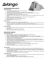
GALAXY
Brand: Vango Pages: 3

SkyRise
Brand: Yakima Pages: 11

955-029
Brand: Kayoba Pages: 9

2000004411
Brand: Coleman Pages: 2

Andi 2 Person
Brand: Nemo Pages: 9

LAGUNA CABANA LOUNGER 2006539
Brand: Backyard Discovery Pages: 44

Ozone
Brand: Outdoor Revolution Pages: 5

W771A
Brand: Ozark Trail Pages: 2

W784.1
Brand: Ozark Trail Pages: 2

DA VINCI SIDE AWNING
Brand: Vango Pages: 2

Chick-Inn Series
Brand: FarmTek Pages: 45

Hercules HC1827PC
Brand: KING CANOPY Pages: 8

Susten 2 XP
Brand: Eureka Pages: 4

DTC-BU6-B
Brand: OZtrail Pages: 16

MONTANA 4 2000001592
Brand: Coleman Pages: 2

CEDAR PASS 9160-908
Brand: Coleman Pages: 2

TITAN SHADE
Brand: Caravan Global Pages: 2

RS 2500
Brand: Webasto Pages: 8


