- 1 -
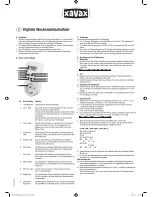
AS-224
Staircase timer
with counter-blockade
Staircase timer AS-224 serves to keep switch-ON lighting of stair-
case, corridor, or any other object for the set time and to switch-
OFF this lighting automatically, upon elapse of this set time.
Turned ON staircase timer supports the lighting during set time
by potentiometer (from 0.5 min. to 10 min.) and upon elapse of
this set time a reduction by half of lighting brightness follows
for about 30 seconds, after that OFF follows (thus an occurrence
of a sudden darkness is avoided, enabling safe approach to the
switch). After switching OFF the lighting there is possibility to
switch it ON again. Function of counter blockade does not allow
to keep the light-ON in case of staircase switch blocking (after
blocking the pushbutton, for example by match, the timer will
count the set time and switch OFF the lighting). Next switching
ON can be after removing the blockade.
Purpose
Functioning
F&F Filipowski sp. j.
Konstantynowska 79/81, 95-200 Pabianice, POLAND
phone/fax (+48 42) 215 23 83 / (+48 42) 227 09 71
www.fif.com.pl; e-mail: [email protected]
Do not dispose of this device in the trash along with other waste!
According to the Law on Waste, electro coming from households free of charge and can
give any amount to up to that end point of collec� on, as well as to store the occasion of
the purchase of new equipment (in accordance with the principle of old-for-new, regar-
dless of brand). Electro thrown in the trash or abandoned in nature, pose a threat to the
environment and human health.