background image

1

Befor

e con

necti

ng th

e TLP

 710C

V to a


powe

r sou

rce, r

efer t

o the

 TLP 

710C

V use

guide

, whic

h is a

vailab

le at 

www

.extro

n.com

.

TLP 710CV and TLE 710 • Setup Guide

Overview

The Extron TLP 710CV 7-inch Cable Cubby

®

 TouchLink

 touchpanel and TLE 710 enclosure provide AV connectivity using 

convenient pullout cables. The TLP 710CV also provides simple and versatile configuration and control for a range of IP Link

®


control systems using a touch screen. The touchpanel communicates through an Ethernet connection to a configurable IP Link 
control processor. Video and audio input is provided by a twisted pair cable connected to an MTP transmitter.

NOTE:

  The network output must connect via a network switch, hub, or router to an Ethernet LAN or the Internet, with 

an Extron IP Link controller on the same network. Suggested controllers include IPL T S series (for example, IPL T S4), 
IPL 250, IPL T CR48, IPL T SFI244, or IPCP series.

The first four pages of this guide provides basic instructions for experienced installers to mount either the TLP 710CV or the 
TLE 710. The last four pages show initial configuration for the TLP 710CV. For reference material and full instructions about 
configuring the touchpanel, see the 

TLP 710CV User Guide

 (see 

www.extron.com

).

Planning


‡

Before making any cuts, select the best location for the 
TLP 710CV or TLE 710.


‡

Ensure that the edge that opens on the lid is oriented correctly.


‡

Ensure there is enough space for all the system cables and 
components, including cable retractors, if they are to be 
installed.


‡

Decide on the method for cutting a hole in the table:


z

Hand router and template


z

CNC wood router


z

Jigsaw and paper template


‡

Verify that you have the correct template or dimensions.


‡

Check all relevant regulations.


z

Ensure the installation complies with local, state, and 
national building and electrical codes.


z

Ensure the installation complies with the Americans with 
Disabilities Act or other accessibility requirements.

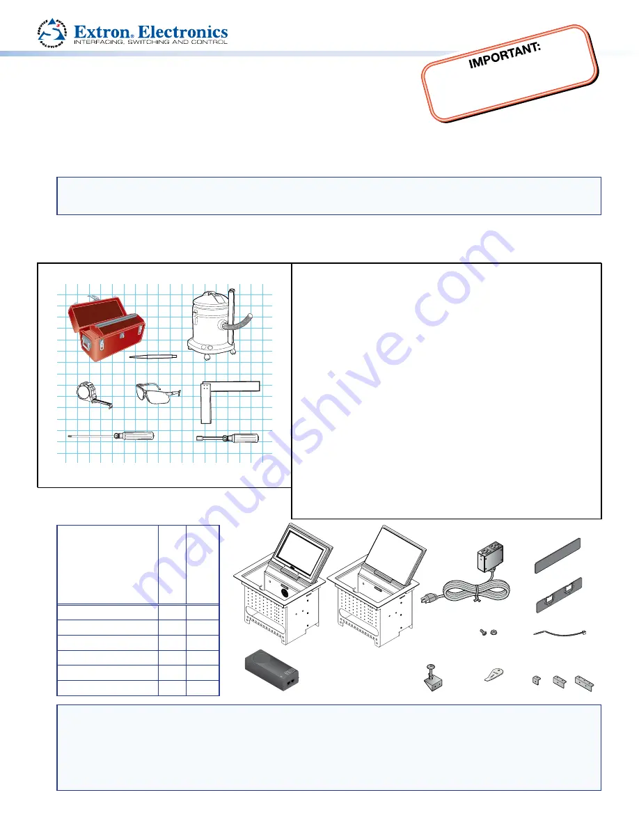
Tools Required for Installation

Safety Glasses

Phillips Screw Driver

Tape Measure

Vacuum Cleaner

1/4" Hex Nut Driver

Marking Pen

Square

Included Parts

W

ith Power 


Module

W

ithout Power 

Module

AC Power Module*

1

0

Pass-through AAPs

3

3

Blank AAPs

6

6

1-space bracket kit

0

1

2-space bracket kit

3

4

3-space bracket kit

1

1

NOTES:

Inside the US, the TLP 710CV may be purchased with or without an AC power module. If required, a power module for 
the TLE 710 must be purchased separately. Outside the US, see 

www.extron.com

 to find an AC power module for 

your country.


Active or Passive AAPs must be purchased separately (see 

www.extron.com

).


The Power over Ethernet injector is provided only with the TLP 710CV.

Table Clamps

Extron 

Removal Tool

Zip Ties

#4−40 Screws

and Nuts

AC Power Module*

Blank AAPs

Pass-thru AAPs

2 Pos

AAP Shelf Bracket Kits

(2 brackets/kit)

3 Pos

1 Pos

PWR LAN OU

T

LAN-IN

AMBER

GREEN

BLINK

POWER ON

POWER 

ACTIV

E

LOAD ERROR

Power over Ethernet

(PoE) Injector

(TLP 710CV only)

TLP 710CV or TLE 350

Extr

on

Extr

on

Summary of Contents for TouchLink TLP 710CV

Page 1: ...y Ensure there is enough space for all the system cables and components including cable retractors if they are to be installed Decide on the method for cutting a hole in the table z z Hand router and template z z CNC wood router z z Jigsaw and paper template Verify that you have the correct template or dimensions Check all relevant regulations z z Ensure the installation complies with local state ...

Page 2: ... see Preparing the Table in the TLP 710CV User Guide There are three methods for cutting the hole in the table Using a hand router Recommended method Use the Extron TLP 710CV routing template part number 70 980 01 Refer to the Routing Template User Guide available at www extron com to prepare the template and use the template to cut the hole NOTE The metal router guide must be purchased separately...

Page 3: ... installed with AAPs on either side 1 Secure the power module into position with 4 40 Phillips head screws and star washers CAUTION Risk of electric shock To ensure good electrical grounding you must use the star washers with the screws 2 Run the cable or conduit to a convenient junction box Extron recommends the circuit be attached to a junction box that is directly wired to the main circuit Step...

Page 4: ...ution when handling and mounting the enclosure 1 Remove the edge grommet protecting the edges of the trim ring and the plastic film on the finished surfaces ATTENTION Do not use isopropyl alcohol or other solvents to clean the Cable Cubby Strong solvents will ruin some finishes 2 Carefully lower the enclosure into the hole cut in the table see Step 2 Cut the Surface on page 2 Ensure the trim ring ...

Page 5: ...he wrong voltages into a socket will damage the TLP 710CV Connecting to the Network Directly Using an external 12 VDC Power Supply If the PoE power supply is not used run a straight through cable from the LAN PoE connection b to a network switch or router Connecting to a Power over Ethernet Power Supply 1 Use a straight through LAN cable to connect the LAN IN socket to a network switch or router 2...

Page 6: ... on page 8 c MTP Video Signal Adjustments Three MTP signal adjustments are available for S video luminance gain VID Y S video chrominance gain C and sharpness S For composite video signals the VID Y adjustment controls the gain d Reset LED provides feedback about the mode status when the user presses the reset button e Controller Communication LED is unlit during normal operation The LED blinks re...

Page 7: ...ifferent screens Main Volume Time Network and Video that can be selected by pressing the appropriate button at the left side of the screen There is also an Exit button at the bottom left corner of the screen for saving changes and leaving the menus Use the screens to adjust the following options for more information see the TLP 710CV User Guide Main Adjusts the Sleep timer Backlight and Auto Backl...

Page 8: ...button in the top left corner highlighted Press and Hold Highlighted Box Until Color Changes 2 Press the highlighted button until it turns gray and a new button is highlighted When all four points have been calibrated the screen reopens to the Main Screen 3 Press Exit to close the on screen menus 4 Reattach the bezel Reset Modes The touchpanel has four reset modes Factory Firmware Mode Run or Stop...

Reviews: