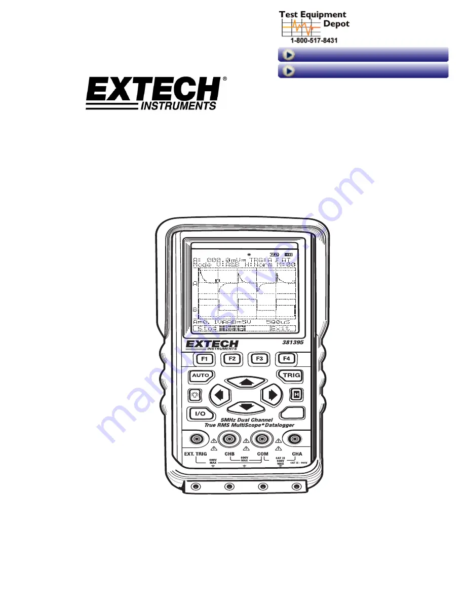
background image


i

U

ser 

M

anual


Model 381395 


5MHz Dual Channel 

True RMS Oscilloscope Datalogger 


FUNC


99 Washington Street 
Melrose, MA 02176 

Phone

 781-665-

1400

Toll Free 1-800-517-8431


Visit us at www.T

estEquipmentDepot.com

Back to the 

Extech 381395

 Product Page

Test Equipment Depot - 800.517.8431 - 99 Washington Street Melrose, MA 02176

FAX 781.665.0780 - TestEquipmentDepot.com 

Summary of Contents for 381395

Page 1: ...r FUNC 99 Washington Street Melrose MA 02176 Phone 781 665 1400 Toll Free 1 800 517 8431 Visit us at www TestEquipmentDepot com Back to the Extech 381395 Product Page Test Equipment Depot 800 517 8431 99 Washington Street Melrose MA 02176 FAX 781 665 0780 TestEquipmentDepot com ...

Page 2: ...STRUMENT 1 5 1 7 1 Standard 1 5 1 7 2 Options 1 5 2 PRODUCT DESCRIPTION 2 1 2 1 THE INPUT TERMINAL AREA 2 2 2 1 1 Caution 2 2 2 1 2 Warning 2 2 2 1 3 600V MAX 2 2 2 1 4 The METER provides 4 input jacks 2 2 2 2 THE KEYS AREA 2 3 2 2 1 Turning power on and off 2 3 2 2 2 AUTO key 2 3 2 2 3 TRIGger key 2 3 2 2 4 Function key 2 4 2 2 5 Command menu keys 2 4 2 2 6 Four arrow keys 2 5 2 2 7 Display back ...

Page 3: ...UIRING THE WAVEFORM 3 5 3 6 1 Recording slow signals over a Long Period of Time 3 5 3 6 2 Selecting AC Coupling for INPUT A 3 5 3 7 TRIGGERING ON A WAVEFORM 3 6 3 7 1 Setting Trigger mode Tmode 3 6 3 7 2 Setting AUTO Trigger Level 3 7 3 7 3 Setting Normal Trigger mode 3 8 3 7 4 Setting Trigger Slope 3 8 3 7 5 Changing the Trigger level Indicator 3 8 3 7 6 Making a single acquisition 3 9 3 8 STORIN...

Page 4: ...time 6 2 6 4 2 Setting the date Error Bookmark not defined 7 SPECIFICATIONS 7 1 7 1 GENERAL SPECIFICATIONS 7 1 7 2 TECHNICAL SPECIFICATIONS 7 2 7 2 1 General Oscilloscope Function Specs 7 2 7 2 2 Data Logger Function Specs 7 3 7 2 3 Digital Multimeter Function Specs 7 3 8 REMOTE PC INTERFACE 8 1 8 1 USB HID DEVICE INSTALLATION 8 1 8 1 1 System Requirements 8 1 8 1 2 Operating System 8 1 8 2 PC USB...

Page 5: ...ATTERY 9 2 9 6 1 Replacing the battery pack 9 3 10 APPENDICES 10 1 10 1 TROUBLESHOOTING GUIDE 10 1 10 2 LCD STATUS INDICATION BY FUNCTION 10 2 10 2 1 Function Menu General Scope Mode 10 2 10 2 2 Data Logger Mode 10 2 10 2 3 Multimeter Record Mode 10 2 10 2 4 Multimeter Relative Mode 10 3 10 2 5 Multimeter Compare Mode 10 3 10 2 6 Multimeter Trend Plot Mode 10 3 10 2 7 System Setup Mode 10 4 10 2 8...

Page 6: ...EC Publication 1010 1 EN 61010 1 1993 Over voltage Category II This instrument features 1 1 1 Universal SCOPE Mode z Dual Channel with Auto Calibration z Sampling Time Single CH mode 50 MS s Dual CH mode 25 MS s z DC to 5MHz Oscilloscope bandwidth z 16 shot waveform and setup memories z Automatic Triggering z Automatic setting for horizontal and vertical divisions z Roll and Single shot modes z Ex...

Page 7: ...e GO NOGO mode and Trend plot z Real Time for MAX or MIN elapsed time for AVG z Meter automatically selects best range instantly Fast Auto range z Data hold and run mode z RPM Duty cycle and Pulse width measurement z True RMS digital Multi meter z Max Voltage between Input and Ground DC or AC 600Vrms z 600V Overload Protection 1 1 4 Frequency Counter z Frequency Range 0 to 10MHz z Accuracy 0 05 5 ...

Page 8: ...r merchantability or fitness for a specific purpose and will not be liable for any direct indirect incidental or consequential damages Extech s total liability is limited to repair or replacement of the product The warranty set forth above is inclusive and no other warranty whether written or oral is expressed or implied 1 3 Precautions z Carefully read the manual before operating this device z Th...

Page 9: ... common test leads black z Disconnect circuit power and discharge all high voltage capacitors before testing resistance and continuity z Only qualified personnel should open the meter case z When replacing fuses use only the specified type and rating z Do not try to operate the Meter if it is damaged Disconnect the power from the equipment and connect the point of purchase for return and repair in...

Page 10: ... Tool Kit The product package is supplied with the following items 1 7 1 Standard z One Meter z Two Test leads z One Lithuim ION Battery installed z One AC Power Rechargeable Adaptor z One CD PC software z Meter to PC USB interface cable z One Carrying case 1 7 2 Options z Rubber Holster ...

Page 11: ...on A brief introduction to the basic operation of the meter is provided below There are four major parts of the METER Each will be addressed in the following sections 4 3 2 1 FUNC 1 The input Terminal area 2 The Keys area 3 The Display area 4 The USB Interface and Power input terminal ...

Page 12: ...al shock or instrument damage do not connect the COM input terminal to any source of more 600V with respect to earth ground 2 1 4 The METER provides 4 input jacks see above 1 Channel A Use Channel A for all single input measurements 2 Common Use Common Black as single ground for low frequency measurements and for ACV DCV Ohm Continuity Hz RPM P W and DTY measurements 3 Channel B For measurements o...

Page 13: ...ontal divisions from Manual to Auto setting 2 In Data Logger and Digital Multimeter modes pressing this key will switch the Range mode to Auto range mode AT 2 2 3 TRIGger key Triggering informs the Meter when to begin displaying a waveform This key is available for use in General Scope Mode only c Trigger Source Ch A or B d Slope Rising or Falling e Trigger setting mode Auto or Normal f Trigger Le...

Page 14: ... item d Select the item e To enter the Setup mode for a particular Function press key GENERAL SCOPE DATA LOGGER c RECORD MODE d RELATIVE MODE e COMPARE MODE f TREND PLOT g SYSTEM SETUP 2 2 5 Command menu keys F1 through F4 are command menu soft keys These keys have a corresponding menu item displayed on the LCD Press a soft key to select the command term shown above the key 2 1 4 3 5 ...

Page 15: ...00Æ100Æ50Æ Æ2Æ1Æ0 5Æ0 2Æ0 1Æ50mV 2 When command menu is in Pos mode Æ The Waveform for Channel A or B can be moved Press to move the waveforms upward Press to move the waveforms downward Or 1 When command menu is in Div mode Æ Horizontal Time Division changes can be made Press to select a higher value in seconds Ex 1 1uSÆ2uSÆ5uSÆ10uSÆ Æ1SÆ2SÆ5S Press to select a lower value in seconds Ex 2 5SÆ2SÆ1...

Page 16: ...ore setups and waveforms in its internal memory for later recall Sixteen 0 15 setup and waveform memories are available Memory mode 2 In Data Logger and Multimeter Mode All readings and waveforms can be held frozen on the display at any time in this mode Or To make Measurement Range changes Press key to select a higher range Ex 1 000 1mVÆ0 001VÆ00 01VÆ000 1V Press key to select a lower range Ex 2 ...

Page 17: ...CATORS DISPLAY area and COMMAND MENU Refer to the Figure below 2 3 1 Special indicators HOLD Freezes the LCD display reading REMOTE Indicates that the meter is communicating with a PC USB Interface BACK LIGHT Back light indicator Charging LINE Charging Battery indicator BATTERY Low battery indicator BUZZER Buzzer indicator 1 2 3 ...

Page 18: ...d Command Menu area Refer to Figure below c ÆGENERAL SCOPEÆ d Press to open Setup PATH Æ ÆSelects GENERAL SCOPE Æ 2 1 Refer to diagram above The settings are shown in this area c 1 Displays the numerical readings If only input A is used only input A readings will display for example c 2 Trigger selection Channel A B and External c 3 Rising or falling edge c 4 Trigger mode Normal or AUTO c 5 Channe...

Page 19: ... division from MANUAL to AUTO 2 4 Command Menu Field f 1 Default command Menu If the key is pressed the command menu changes to Toggle the command Menu items Div and Pos using the key f 2 Press key to display the TRIGGER command menu 2 5 The Setup mode for the Scope g 1 AC DC Coupling for Channel A g 2 AC DC Coupling for Channel B g 3 Set CHA CHB or CHA CHB for Vertical mode g 4 Set NORMal or ROLL...

Page 20: ... current Function indicator 3 3 Display of Datalogger info number of readings time and measurement data e 1 Displayed or for the sampling type e 2 Logged data Record Number e 3 Time of logged data e 4 Numerical reading e 5 Logged data e 6 End of Data shown when last data point has been reached 3 4 The Data Logger Command Menu f 1 Open the Data Logger Setup mode f 2 Erase the displayed logged data ...

Page 21: ... and DMM Function d Refer to Data Logger section 3 Number of records and the time stamp e 1 The displayed value updates only when a new maximum value is detected e 2 The displayed value updates only when a new average value is detected e 3 The displayed value updates only when a new minimum value is detected e 4 Total number of data e 5 Total elapsed time 4 The Command Menu for Record mode f 1 Ope...

Page 22: ...Numerical Field Data Logger and DMM Function d Refer to Data Logger section 3 Displays the Relative data and time e 1 Reference value e 2 Difference value Difference Measured value Reference REF e 3 Error rate ERR Difference Reference x 100 e 4 The mean error e 5 Total elapsed time 4 The Command Menu for the Relative mode f Refer to the Record mode 5 The Setup mode for Relative g 1 Set the Measure...

Page 23: ...nput value is lower than the low limit PASS if the input value is within the high and low limit values and HI if the input is greater than the high limit 3 Display of the Comparison data and time e 1 To be set value for HI limit e 2 To be set value for LOW limit e 3 Reading value e 4 Total pass muster e 5 Total elapsed time 4 The Command Menu for Relative mode f Refer to Record mode 5 The Setup mo...

Page 24: ...efer to Data Logger section 3 Display of the graph trend plot e 1 Horizontal Division per div e 2 Displays the graph with the reference value as the center value 4 The Command Menu f 1 The Reference value horizontal and vertical axis values REF H Div V Div are displayed f 2 Erase the graph f 3 Starts the graph plot using REF value as the centerline 5 The Setup mode for the Trend plot g 1 or g 2 Th...

Page 25: ...selection 3 BAUD RATE BPS USB Baud rate selection 4 TIME SET Set current time 5 DATE SET Set Date of today 6 CONTRAST LCD Contrast adjust 2 3 3 The Command Menu The command menu is changed depends on the function with each function Mode PATH Command Menu Function Menu Div ÆG ScopeÆ Pos ÆG ScopeÆ Æ Trigger ÆG ScopeÆ Æ General Scope Store Recall ÆG ScopeÆ Æ Data Logger ÆD LoggerÆ Record Relative Com...

Page 26: ... a PC over a Universal Serial Bus USB Connect the meter to the PC using the supplied communication cable The TRS tip ring sleeve phone plug end of the cable connects to the meter top and USB end connects to the PC USB port 2 4 2 Power Adaptor Input Terminal If an AC DC power adapter is to be used ensure that the adapter is plugged into an appropriate live power source ...

Page 27: ...ey for 2 3 seconds 4 The meter powers up configured as it was at last power down 3 2 Changing Backlight 1 Press Backlight ON 2 Press Backlight OFF Note Using the meter without the backlight increases battery life by 1 hour approximately 3 3 Selecting GENERAL SCOPE in the Menu Follow steps c through e to open a menu and choose an item c Open the FUNCTION menu General Scope Data Logger Multimeter 4 ...

Page 28: ...Select the item f Exit PATH Æ Æ Æ 3 4 1 Set Frequency measurement for CHA To choose a Frequency measurement for Channel A perform the following c Input jack Plug the black test lead into the COM input jack and plug the red test lead into the CHA input jack d Start Display Æ Î e Highlight Hz Hz f Set Hz Hz g Exit h Observe that Hz is now the main reading The Frequency unit appears at the top left c...

Page 29: ... increases CHA or CHB vertical division 2 Pressing decreases CHA or CHB vertical division 3 Pressing will change the division from MANUAL to AUTO mode 3 5 2 Changing the Horizontal division Time Base c With the menu as shown at right d Change command Menu Pos to Div e or Change the Horizontal Division Time base Pressing key decreases Horizontal division H div 5SÆ2SÆ1SÆ500mSÆ Æ50uSÆ20uSÆ10uSÆ5uSÆ2u...

Page 30: ...ositioning the Waveform of CH B on the Screen c With the menu at right press key to change the command menu Div to Pos d To change the Division command menu from CHA to CHB e Next procedure Same as example above for Positioning CH A Wave on the Screen PATH Î Î or 1 Pressing moves the waveform of Channel B downward 2 Pressing moves the waveform of Channel B upward 3 5 5 Positioning the Trigger Poin...

Page 31: ...e d Highlight ROLL mode e Set the ROLL mode f Exit PATH Î Î Î The ROLL mode function supplies a visual log of waveform activity and is especially useful when measuring lower frequency waveforms Note ROLL MODE operates when the horizontal division is between 1sec and 5 sec 3 6 2 Selecting AC Coupling for INPUT A d Highlight AC for INPUT A e Set the AC coupling for INPUT A f Exit PATH Î Î Î Use AC c...

Page 32: ...ct a Trigger mode z Define the condition for waveform updates The display icons on the top line right side of the LCD identify the trigger parameters currently used Trigger icons on the screen indicate the trigger level and slope 1 Trigger selection Channel A B and External 2 Rising or falling edge 3 Trigger mode Normal or AUTO Trigger level indicator Trigger point indicator 3 7 1 Setting Trigger ...

Page 33: ...it PATH Î Î Î Î 3 7 2 Setting the AUTO Trigger Level For quick operation use the AUTO trigger mode to trigger on nearly all signals automatically To optimize the trigger slope manually perform the following b Default command menu c Open the Trigger command menu d Open the Trigger Setup e Highlight AUTO f Set AUTO g Exit PATH Î Î Î Î ...

Page 34: ... Slope of a waveform e Highlight or f Set or g Exit PATH Î Î Î Î 3 7 5 Changing the Trigger level Indicator For NORMal Trigger mode b Default command menu c Open the Trigger command menu d or Adjust the Trigger Level continuously Observe the Trigger level indicator on the rightmost time division line e Exit PATH Î or 1 Pressing moves the Trigger level indicator downward 2 Pressing moves the Trigge...

Page 35: ... performs a single shot One time screen update e Return to normal Trigger mode PATH Î Î 3 8 Storing and Recalling Screens The meter can store setups and waveforms for later recall Sixteen 0 15 setup and waveform memories are available 3 8 1 Storing Screen To store a screen perform the following b Default command menu c Open the Memory MEM menu c Memory Menu Store Recall Exit d Memory Address 0 15 ...

Page 36: ...nd menu c Open the Memory MEM menu c Memory Menu Store Recall Exit d Memory Address 0 15 M 00 d Memory field M 00 appears at the top right corner of the display area Select the memory address from which to recall the screen e Recall the screen PATH Î Î The result will be a fixed image and therefore can not be edited or otherwise changed 2 1 ...

Page 37: ...built in USB interface Up to 17 000 measurements can be stored in memory PATH Î DATA LOGGER Î Æ 4 1 Items in the Data Logger Setup menu Follow steps c through i to open a menu and choose an item c Open the FUNCTION menu d Use the arrow keys to highlight DATA LOGGER e Set and Open the Data Logger f Open the Data Logger Setup g Use the arrow keys to highlight an item h Set the desired item i Exit PA...

Page 38: ...ve the Cursor to highlight the most significant digit Ex 2 S Time Sec 00000 k Press key to increase key to decreases the highlighted digit Ex 3 S Time Sec 00010 l Exit PATH Î Î Î Î Î Î Î Î Î 4 1 3 Change the Start Stop Address Example Set the Start address from 10001 to 12001 g Use the arrow keys to highlight Sampling Time or Start Stop Address h Press key to switch to the Edit mode Ex 1 START ADD...

Page 39: ...Function Ex 1 DTYÆP WÆRPMÆFRQÆBZÆOHMÆACVÆ DCV Press key to change the Measurement Function Ex 2 DCVÆACVÆOHMÆBZÆFRQÆRPMÆP WÆDTY 7 Select the auto range function by pressing key or use keys to select the desired range Press key to change to a higher range Ex 1 000 1mVÆ0 001VÆ00 01VÆ000 1V Press key to change the lower range Ex 2 000 1VÆ00 01VÆ0 001VÆ000 1mV Press key to choose the Auto range AT mode...

Page 40: ...e Ex 2 000 1VÆ00 01VÆ0 001VÆ000 1mV Or Measurement Function change Press the key to change the Measurement Function Ex 3 DTYÆP WÆRPMÆFRQÆBZÆOHMÆACVÆ DCV Press the key to change the Measurement Function Ex 4 DCVÆACVÆOHMÆBZÆFRQÆRPMÆP WÆDTY 4 3 Recall Data To recall data from the meter s internal memory perform the following c Open the FUNCTION menu d Use the arrow keys to highlight DATA LOGGER e Set...

Page 41: ...taken over a period of time Real Time for MAX or MIN elapsed time for AVG 5 1 2 RELATIVE MODE c Æ RELATIVE MODE Æ d Press to open Setup e Press to change Edit mode PATH Æ ÆSelects RELATIVE MODE Æ In this mode the meter records and displays reference REF difference DIF and error ERR values from measurements taken over a period of time The relative mode measures to what degree the input value deviat...

Page 42: ...the low limit PASS if the input value is within the high and low limit values and HI if the input is greater than the high limit 5 1 4 TREND PLOT c Æ TREND MODE Æ d Press to open Setup e Press to change Edit mode PATH Æ ÆSelects TREND PLOT Æ Displays the trend graph with the reference value as the center value F1 SetUp The Reference value horizontal and vertical axis values REF H Div V Div are dis...

Page 43: ...rements 5 2 1 DC V z Applications DCV Voltage of batteries or DC circuits can be measured z Measuring ranges 4 ranges from 1 000mV to 1 000V z Measurement procedure 1 Insert the BLACK test lead into the input socket marked as COM 2 Insert the RED test lead into the input socket marked as CHA 3 Open the FUNCTION menu 4 Highlight Digital Multimeter Record Relative Compare or Trend 5 Open the selecte...

Page 44: ...asuring ranges Four 4 ranges from 1 000mV to 750V z Measurement procedure 1 Insert the BLACK test lead into the input socket marked as COM 2 Insert the RED test lead into the input socket marked as CHA 3 Change the mode to Digital Multimeter skip this step if Digital Multimeter mode is set Path Î Î Record Relative Compare mode or Trend plot 4 Select ACV with the or keys The ACV appears at the top ...

Page 45: ...arked as CHA 3 Change the mode to Digital Multimeter skip this step if Digital Multimeter mode is set Path Î Î Record Relative Compare mode or Trend plot 4 Select OHM with the and keys The OHM icon appears at the top left corner of the display area 5 Select the auto range function by pressing key or use keys to select the desired range 6 Connect test leads to the source signal and observe the read...

Page 46: ...uency of an AC circuit is measured z Measuring ranges Full Auto Range Six 6 ranges from 100Hz to 10MHz z Measurement procedure 1 Insert the BLACK test lead in the input socket marked COM 2 Insert the RED test lead in the input socket marked CHA 3 Change the mode to Digital Multimeter skip this step if Digital Multimeter mode is set Path Î Î Record Relative Compare mode or Trend plot 4 Select FRQ w...

Page 47: ...Digital Multimeter mode is set Path Î Î Record Relative Compare mode or Trend plot 4 Select P W with the or key The P W appears at the top left corner of the display area 5 Connect test leads to the source signal and observe the reading shown on the display 5 2 8 Duty Cycle z Applications Duty Cycle is measured z Measurement procedure 1 Insert the BLACK test lead in the input socket marked COM 2 I...

Page 48: ...estored When ON an audible beep will sound when any front panel key is pressed Path Î SYSTEM SETUP Î 6 2 Auto Power Off The Auto Power Off mode turns the meter off automatically after a period of 20 minutes of inactivity This feature is in place to conserve battery life 6 3 Set the BAUD RATE BPS of USB To change the BAUD Rate BPS c Press ÆSYSTEM SETUPÆ to access SYSTEM SETUP d Use the arrow keys t...

Page 49: ...ars at the bottom left corner of the display area 3 Press key 4 Press or key The cursor indicates the selected digit hh mm ss 5 Press or to set the time Move the blinking cursor left with the key and right with the key Pressing the key increases the value of the blinking digit Pressing the key decreases the value of the blinking digit 6 4 2 Setting the Date DATE SET allows the user to set the date...

Page 50: ...r key The cursor indicates the digit that is ready for edit dd mm yy 5 Use the or keys to set the date Move the blinking cursor to the left with the key and to the right with the key Pressing the key will increase the value of the blinking digit Pressing the key will decrease the value of the blinking digit ...

Page 51: ...4 F 28 C z Max Voltage Input and Ground DC or AC 600Vrms z Basic DC Accuracy 0 3 z Scope Bandwidth 5 MHz z Meter AC Bandwidth 20 kHz z Power Supply Li ION Battery 3 7V z Battery Life 4 Hours with Backlight OFF 3 Hours with Backlight ON z Battery Charge Time 3 Hours approx z Battery Charge information Class 2 transformer Input 120 240V AC 50 60Hz Output 5V DC 1A z Display Type Super Twist 132 x 128...

Page 52: ...de Record Length 512 in single shot mode 256 in all other modes Samples Division 25 Update Rate Real Time Modes Single shot Roll Normal Accuracy 0 01 Sweep Rate 1uS to 5S in 1 2 5 sequence z Vertical Bandwidth 5MHz Resolution 8 Bit Channels Dual Coupling AC DC Input impedance 1 MΩ Accuracy 3 1 Pixel Max Input Volts DC or AC 600Vrms Volt Division 50 mV to 500V in 1 2 5 sequence z Triggering Type CH...

Page 53: ...DMM Range Resolution Accuracy Impedance 50m 0 1 0 2 1000mV 0 1mV 0 5 1 2 10V 0 001V 5 10 20 100V 0 01V 0 3 3 50 100 200 1000 1000V 0 1V 0 5 5 1 MΩ z AC V Accuracy Scope V Div DMM Range Resolution 50 450Hz 0 45k 5kHz 5k 20kHz Impedance 50m 0 1 0 2 500mV 0 1mV 0 5 1 2 5V 0 001V 5 10 20 50V 0 01V 3 5 5 50 100 200 500 750V 0 1V 0 75 5 2 5 N A 1 MΩ For Voltages 200V in the range 5 kHz to 20 kHz the acc...

Page 54: ...V DC or AC rms z Frequency Full Auto Range Range Resolution Accuracy Overload protection 100 Hz 0 01 Hz 1 kHz 0 0001 kHz 10 kHz 0 001kHz 100 kHz 0 01kHz 1 MHz 0 0001MHz 10 MHz 0 001MHz 0 05 5 600V DC or AC rms z RPM Range Resolution Accuracy 0 9 999 1 RPM 0 05 5 z Pulse Width Full Auto Range Range 2uS 500mS Pulse Width 2uS z Duty Range 25 75 ...

Page 55: ...stem z Microsoft WindowsTM XP or above 8 2 PC USB port Connection 1 Connect the USB cable to the meter and to the PC 2 Press and hold the I O key for 1 to 2 seconds to power the meter 8 2 1 Human Interface Device When the meter is connected to the PC and then powered up the PC should display Found New Hardware and automatically install the Human Interface Device HID driver HIDs do not require a cu...

Page 56: ...ert the software CD into the CD ROM drive of the PC 2 Open Windows Explorer and double click the CD ROM drive 3 Auto Run or simply double click on Setup exe Step 1 Choose Setup Language Step 2 Preparing to Install Step 3 Welcome Step 4 Ready to Install the Program Step 5 Installing Software Step 6 Install Wizard Completed ...

Page 57: ...ware 1 Connect the meter to the PC using the supplied USB cable 2 Turn the Meter ON 3 Run the software The Software window will open as shown below 8 4 1 Oscilloscope Mode 1 Click the LINK Button and then the Start Button LINK Button Screen Print Set the System Time and Date Start Stop Button 1 2 3 4 ...

Page 58: ...Position Division Auto ON Off and DC coupling Channel B Vertical Position Division Auto ON Off and DC coupling Horizontal Division and Trigger Horizontal Division Auto Trigger Level Source and Position Measurement Function DCV ACV OHM BZ Hz RPM Pulse Width and Duty Storing and Recalling Screens 8 4 2 DMM Data Logger Mode 1 Click the DMM Logger tap LINK Button Start Stop Button 2 3 1 6 5 4 7 8 2 1 ...

Page 59: ... 3 Display Mode for DMM Data Logger Mode DATA LOGGER MODE RECORD MODE z Sample Method Time Sample interval Mode Peak Peak Detect Mode z Sample Time Sampling interval time 1Sec to 9 999Sec z Start Address Set the Start Address z Stop Address Set the Stop Address to 17 000 Set Set Button for Data Logger Clear Erase for Logged data of display Recall Displays stored readings and buffer statistics Star...

Page 60: ... Limit Set value for HI limit z LO Limit Set value for LOW limit z Reading Reading value z Pass Muster Total passes z Elapsed Time Total elapsed time SetUp Open Setup mode for Compare mode Reset All data set to zero Pause Freezes the displayed value Hold Freeze the screen at any time TREND PLOT MODE z Plot Mode Line or Dot z Offset The centerline value on the trend graph z V Division V DIV is the ...

Page 61: ...safe work area Use grounded static control table mats and always wear a grounded wrist strap Handle boards by their nonconductive edges only store plastic vinyl and Styrofoam objects outside of the work area 2 Store and transport all static sensitive components and assemblies in static shielding bags or containers Static shielding bags and containers protect components and assemblies from direct s...

Page 62: ...bration and inspection For more information please contact the manufacturer 9 6 Replacing Disposing of the LI ION Battery Warning To avoid electrical shock remove the test leads and probes before replacing the battery pack Caution Handle the PCB Assembly by its edges or while wearing gloves Note This instrument contains a LI ION battery pack Do not dispose of this battery pack with other solid was...

Page 63: ...er Power OFF Make sure the meter is turned off and unplugged from the power Adaptor Remove Screws Remove the three screws from the bottom of the case 3 pcs Remove the PCB Assembly Remove the PCB Assembly by releasing the four snap retainers 2 Remove Rubber key and Battery Pack Rotate the PCB Assembly 180 degrees Remove the Rubber Key Remove the Battery Pack Remove the battery plug from the connect...

Page 64: ...ys do not respond to presses or if the display is unreadable remove the power source while the instrument is on and then restore operations after a 15 minute wait period 3 If difficulties continue check the connections 4 If the meter s display is frozen when trying to control the trigger level z In normal NORM mode the trigger level must be the same level as the waveform The Meter does not trigger...

Page 65: ...uary 2008 10 2 10 2 LCD STATUS INDICATIONS BY FUNCTION 10 2 1 Function Menu General Scope Mode Function Menu General Scope Æ Æ 1 Æ Æ Æ 10 2 2 Data Logger Mode Data Logger Æ Æ 2 Æ Æ Æ Æ Æ Æ Æ 10 2 3 Multimeter Record Mode Record Mode Æ Æ 3 Æ Æ Æ ...

Page 66: ...5 Version 1 0 January 2008 10 3 10 2 4 Multimeter Relative Mode Relative Mode Æ Æ 4 Æ Æ Æ Æ Æ Æ Æ 10 2 5 Multimeter Compare Mode Compare Mode Æ Æ 5 Æ Æ Æ Æ Æ Æ Æ 10 2 6 Multimeter Trend Plot Mode Trend Plot Æ Æ 6 Æ Æ Æ Æ Æ Æ Æ ...

Page 67: ...igger Setup Mode Trigger Setup Æ Æ 1 Æ Æ Æ Æ Æ 99 Washington Street Melrose MA 02176 Phone 781 665 1400 Toll Free 1 800 517 8431 Visit us at www TestEquipmentDepot com Back to the Extech 381395 Product Page Test Equipment Depot 800 517 8431 99 Washington Street Melrose MA 02176 FAX 781 665 0780 TestEquipmentDepot com ...

Reviews: