EWM TIGSPEED OSCILLATION DRIVE 45 COLDWIRE, Operating Instructions Manual
Introducing the EWM TIGSPEED OSCILLATION DRIVE 45 COLDWIRE - a powerful welding tool designed to deliver precise and efficient results. For seamless operation, access our Operating Instructions Manual, available for free download at manualshive.com. This comprehensive manual provides step-by-step guidance, ensuring optimal performance for your welding projects.
Share
Download


Reviews:
No comments
Related manuals for TIGSPEED OSCILLATION DRIVE 45 COLDWIRE

Q9000 series
Brand: Quadratec Pages: 12

Platform
Brand: ClearOne Pages: 2

65626
Brand: Gibson Pages: 2

TWN4 CONFIG PROGRAMMER
Brand: Elatec Pages: 7

FIRE-LITE series
Brand: Isokern Pages: 59

LogBox AA
Brand: B+B Sensors Pages: 2

RSS-233
Brand: Ridewell Suspensions Pages: 16

X-Pro 1000
Brand: SuperFish Pages: 12

620 STANDARD
Brand: FAAC Pages: 3

77 77 29
Brand: Conrad Pages: 2

DD-6006
Brand: X10 Pages: 27

GSM-R4-DIN
Brand: SEA Praha Pages: 5

DURASTALL 30
Brand: Mustee Pages: 6
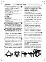
Pickup Mute PM1X
Brand: Yamaha Pages: 2

Ranger X2
Brand: Backfire Pages: 20

NF4027P
Brand: KEYKING Pages: 34

PLATUNUM RANGE
Brand: Waterbox Pages: 25

OM-DAQXL-1 Series
Brand: Omega Pages: 85


