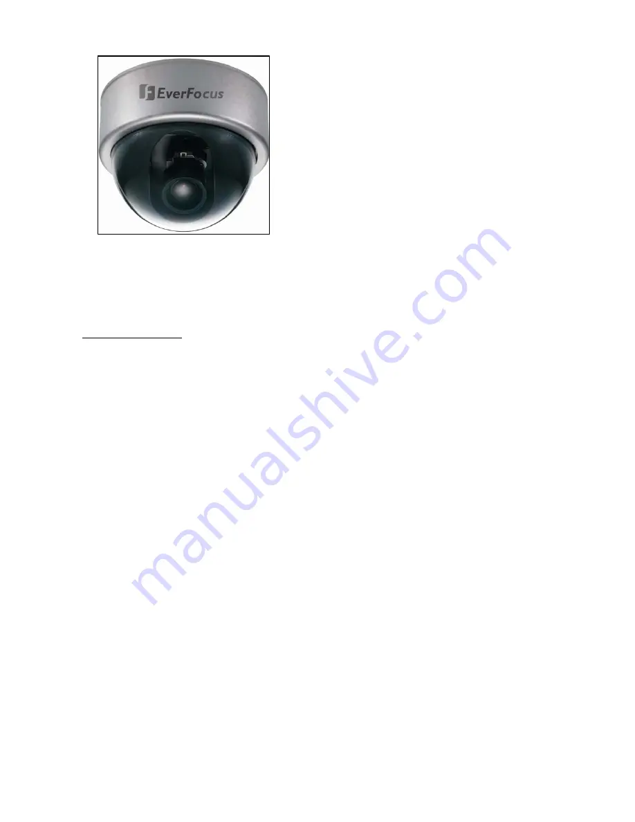
background image


EVERFOCUS


560 TVL True Day/Night Indoor 

Vandal Color Camera 

Operation Instructions 


Model No. 

ED550 


Please read this manual first for correct installation and operation. This manual should be retained for future 

reference. The information in this manual was current when published. The manufacturer reserves the right to 

revise and improve its products. All specifications are therefore subject to change without notice.   


PRECAUTIONS 

1. 

Do not install the camera near electric or magnetic fields.   

Install the camera away from TV, radio transmitter, magnet, electric motor, transformer, audio speakers 

since the magnetic fields generate from above devices will distort the video image. 


2. 

Never disassemble the camera nor put impurities in it. 

Disassembly or impurities may result in trouble or fire. 


3. 

Never face the camera toward the sun. 

Direct sunlight or severe ray may cause fatal damage to sensor and internal circuit. 


4. 

Keep the power cord away from wet and never touch the power cord with wet hands. 

Touching the wet power cord with hands or touching the power cord with wet hands may result in electric 

shock. 


5. 

Never install the camera in areas exposed to water, oil or gas. 

Water, oil or gas may result in failure, electric shock or file. 


6. Cleaning 

Do not touch the surface of sensor by hand directly. Use a soft cloth to remove the dirt from the camera 

body. Use lens tissue or a cotton tipped applicator and ethanol to clean the sensor and the camera lens. 


7. 

Do not operate the camera beyond the specified temperature, humidity or power source ratings.   

Use the camera at temperatures within 0

 ~ 40


(32

 ~ 104

℉)


and 20%~80% Humidity. The input 

power source is 12VDC/24VAC. 


Summary of Contents for ED550

Page 1: ...in it Disassembly or impurities may result in trouble or fire 3 Never face the camera toward the sun Direct sunlight or severe ray may cause fatal damage to sensor and internal circuit 4 Keep the power cord away from wet and never touch the power cord with wet hands Touching the wet power cord with hands or touching the power cord with wet hands may result in electric shock 5 Never install the cam...

Page 2: ...LLATION 9 4 CAMERA SETUP OPERATIONS 10 4 1 Setup Button 10 4 2 Display Close the user setup menu screen 11 5 USER SETUP 12 5 1 Lens 12 5 2 Shutter 12 5 3 White Balance Control 14 5 4 Backlight 15 5 5 AGC Auto Gain Control 15 5 6 DNR Dynamic Noise Reduction 16 5 7 SENS UP 16 5 8 Special 17 5 8 1 CAMERA ID 18 5 8 2 COLOR ADJ 19 5 8 3 SYNC 19 5 8 4 MOTION DETECTION 19 5 8 5 PRIVACY 22 5 8 6 MIRROR 24...

Page 3: ... 3 5 8 7 SHARPNESS 24 5 8 8 RESET 24 5 8 9 RETURN 25 5 9 Exit 25 ...

Page 4: ... Main Features Excellent super high resolution technology with 560 TVL Advanced 16 bit Digital Signal Processor DSP delivers excellent picture quality and performance True Day Night function with IR cut filter ED550T Day Night function ED550D Built in DNR Dynamic Noise Reduction for noise reduction and a 70 saving of disk storage The starlight Super high sensitivity of 0 002 lux F 1 2 is achieved ...

Page 5: ...ity Enhanced Back Light Comp Yes Off Low Middle High selectable Auto Gain Control Yes Off Low Middle High selectable DNR Yes Off Low Middle High selectable Auto White Balance ATW 2500 8300 k AWC Manual Gamma Correction 0 45 Flickerless Yes Video Output 2 video outputs BNC 1 0Vp p 75ohm Additional testing video output 1 0Vp p 75ohm Sync Mode Line Lock Internal sync Motion Detection Off On 4 zone po...

Page 6: ... 6 1 4 Dimensions 2 NAMES AND FUNCTIONS OF PARTS 2 1 Front Panel Note Internal Sensor is a Day Night Switch Sensor Internal Sensor ...

Page 7: ... 7 ...

Page 8: ...oaxial cable with BNC female connector at backside of the camera 2 Second Video Output Connector When installing the camera you can use second video connector to connect a portable monitor this will allow you to easily adjust camera angle 3 Adjust the Switch to Left direction 4 Adjust the Switch to Down direction 5 Adjust the Switch to Right direction 6 Adjust the Switch to Up direction 7 Press th...

Page 9: ...first Fix 3 screws of the bracket firmly to wall or ceiling Adjust the camera to best angle for viewing Use the tact switcher at the back panel to make any adjustment if needed Finally place the cover back to the camera Ceiling Mount Wall Mount ...

Page 10: ... be set z Down Adjust the switch to move the cursor downwards This is used to select the item need to be set z Right Adjust the switch to right direction This is used to select or adjust the parameters of the selected item z Left Adjust the switch to left direction This is used to select or adjust the parameters of the selected item z Set button This button is used to enter setup menu If the item ...

Page 11: ...itch to the sub menu for further settings Please refer to the figure below NOTE For those selected items with sign in the end they have the sub menu for further settings IV Return to previous page Press SET button to return to previous page V Close the menu screen To close the menu screen move the cursor to select EXIT and press the SET button Sub Menu Main Menu SETUP LENS DC SHUTTER ___ WHITE BAL...

Page 12: ...ch to DOWN direction 2 Select the shutter mode by adjusting the switch to LEFT or RIGHT direction Ö FLK Please select FLK mode when flickering occurs on the screen because of an irregular balance between illumination and frequency NTSC model 1 100 PAL model 1 120 SETUP LENS DC SHUTTER ___ WHITE BAL ATW BACKLIGHT OFF AGC MIDDLE DNR LOW SENS UP AUTO SPECIAL EXIT NOTE 1 ED550 does not support Manual ...

Page 13: ...l the settings NOTE 1 When selecting DC lens the shutter speed is fixed as 1 60 for NTSC and 1 50 for PAL 2 When MANUAL mode is on the SENS UP function will be disabled SETUP LENS MANUAL SHUTTER FLK WHITE BAL ATW BACKLIGHT OFF AGC MIDDLE DNR LOW SENS UP ___ SPECIAL EXIT BRIGHTNESS BRIGHTNESS 25 SHUTTER MANUAL 1 50 SETUP LENS MANUAL SHUTTER MANUAL WHITE BAL ATW BACKLIGHT OFF AGC MIDDLE DNR LOW SENS...

Page 14: ... and the light source are changed you need to adjust the white balance again Ö MANUAL The manual adjustment mode enables a more precise adjustment Please select ATW or AWC first Then change to manual adjustment mode and press the SET button Set the suitable color temperature and increase or decrease the red and blue color values at the same time while checking the color changes of the object NOTE ...

Page 15: ...LIGHT function does not operate 5 5 AGC Auto Gain Control 1 Please direct the arrow to point to AGC on the SETUP menu by adjusting the switch to UP or DOWN direction 2 Select the mode you would like to operate by adjusting the switch to LEFT or RIGHT direction The more the level of gain increases the brighter the screen and the level of noise increases as well Ö HIGH The gain increases from 6dB up...

Page 16: ...ise level Ö LOW Little reduction in noise level with nearly no ghost image Default value is LOW Ö MIDDLE Just enough reduction in noise levels without causing much ghost imaging Ö HIGH Huge reduction in noise level which may cause much ghost imaging 5 7 SENS UP SENS UP is used to keep a brilliant vivid screen image by automatically detecting changes in the level of light under low light level cond...

Page 17: ...will be disabled NOTE 1 The maximum storage magnification in low light level movement situations can be adjusted by pressing the SETUP button in AUTO mode 2 The screen becomes brighter when the magnification increases yet the after image increases as well 3 Please be noted that spots and noise may appear if storage magnification increases when SENS UP is operating This is a normal phenomenon SETUP...

Page 18: ...o display the name Move the cursor onto POS and press the SET button The name will appear at the top left hand corner Please adjust the switch toward 4 directions to find the desired position to display the name 6 If you would like to cancel the ID inputted please move the cursor to CLR and all the letters inputted will be deleted 7 Select END and press SET button to complete ID input _ _ _ _ _ _ ...

Page 19: ...4 MOTION DETECTION ED550 camera enables you to observe movements of objects in 4 different places on the screen the message MOTION DETECTED appears on the screen when movement is detected therefore this helps to improve supervision efficiency The camera detects an object s movement by sensing discrepancy of outline 1 Please direct the arrow to point to MOTION DET by adjusting the switch to UP or D...

Page 20: ...T direction to adjust the value for size of the area to be detected z Additionally it is possible to change the position of the area to be detected Please refer to the following example for detailed steps on moving AREA1 to center 1 The original position of AREA1 was TOP 10 DOWN 25 LEFT 20 and RIGHT 40 MOTION DETECTION AEREA SEL AREA1 AREA STATE ON TOP 10 DOWN 25 LEFT 20 RIGHT 40 SPECIAL CAMERA ID...

Page 21: ...OWN 45 LEFT 20 and RIGHT 40 4 Increase RIGHT scale value by 20 AREA1 position after change is TOP 30 DOWN 45 LEFT 20 and RIGHT 60 5 Increase LEFT scale value by 20 AREA1 position after change is TOP 30 DOWN 45 LEFT 40 and RIGHT 60 z In order to save the changes and complete the setting press the SET button This allows you to return to the previous menu AREA1 AREA1 AREA1 AREA1 ...

Page 22: ...e lighter the cover area z Please adjust the switch to UP or DOWN direction to move between TOP DOWN LEFT and RIGHT for adjusting the size of the area to be covered z Please adjusting the switch to LEFT or RIGHT direction to adjust the value for size of the area to be covered z Additionally it is possible to change the position of the area to be covered Please refer to the following example for de...

Page 23: ...45 LEFT 20 and RIGHT 40 3 Increase TOP scale value by 20 AREA1 position after change is TOP 30 DOWN 45 LEFT 20 and RIGHT 40 4 Increase RIGHT scale value by 20 AREA1 position after change is TOP 30 DOWN 45 LEFT 20 and RIGHT 60 5 Increase LEFT scale value by 20 AREA1 position after change is TOP 30 DOWN 45 LEFT 40 and RIGHT 60 AREA1 AREA1 AREA1 AREA1 AREA1 ...

Page 24: ...mely it may affect the video image and cause noise ON Enable the SHARPNESS mode OFF Disable the SHARPNESS mode z Please press the SET button z The available range of level is 0 31 5 8 8 RESET Reset to the default level SHARPNESS LEVEL 8 SPECIAL CAMERA ID OFF COLOR ADJ SYNC INT MOTIION DET OFF PRIVACY OFF MIRROR OFF SHARPNESS ON RESET RETURN SPECIAL CAMERA ID OFF COLOR ADJ SYNC INT MOTIION DET OFF ...

Page 25: ...o the SETUP menu 5 9 Exit Save all the setting menus and exit SPECIAL CAMERA ID OFF COLOR ADJ SYNC INT MOTIION DET OFF PRIVACY OFF MIRROR OFF SHARPNESS ON RESET RETURN NOTE If you quit the Menu without pressing EXIT all the settings you previously did will NOT be saved ...

Page 26: ...s com Your EverFocus product is designed and manufactured with high quality materials and components which can be recycled and reused This symbol means that electrical and electronic equipment at their end of life should be disposed of separately from your household waste Please dispose of this equipment at your local community waste collection recycling centre In the European Union there are sepa...

Reviews: