EVBox Smart Charging, Installation Manual
EVBox Smart Charging offers an intelligent and efficient electric vehicle charging solution. Enhance your charging experience with our comprehensive Installation Manual that you can conveniently download for free from our website. Learn about every aspect of our innovative product and unleash the full potential of your charging solution.
Share
Download


Reviews:
No comments
Related manuals for Smart Charging
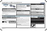
883-0105-12
Brand: Xantrex Pages: 2

BC-100B
Brand: Sibata Pages: 4

EOS 0606i AC/DC
Brand: Hyperion Pages: 7

ACC-001-33THK
Brand: DT Research Pages: 2

B2B1230
Brand: OLYS Pages: 10

Charge Time ISP99S
Brand: ION Pages: 10

RP-UM002
Brand: Ravpower Pages: 23

Twinbox GTB Series
Brand: GARO Pages: 35

Uni 2/4 slim line
Brand: Hama Pages: 2

HCH-XL1-CHG
Brand: GTS Pages: 2

Karate Nighthawk AC/DC
Brand: YUKI MODEL Pages: 44

FLEXPOWER
Brand: Master-force Pages: 16

10111787
Brand: Chauvet DJ Pages: 28

INFINEA BLUEPAD
Brand: Infinite Peripherals Pages: 47

WA3739
Brand: Worx Pages: 16

On channel 100
Brand: GEONAUTE Pages: 1

Mini 90Watt
Brand: Fresh 'N Rebel Pages: 10

Akkupack SF9000
Brand: Schwaiger Pages: 24


