EuroPower DC12V50AMP, User Manual
The EuroPower DC12V50AMP is a high-quality power supply unit suitable for various electronic applications. This product offers efficient and reliable performance, ensuring optimal power distribution. For complete instructions and guidelines, you can conveniently download the user manual for free from our manualshive.com to maximize your experience with this product.
Share
Download


Reviews:
No comments
Related manuals for DC12V50AMP

85-2500
Brand: Napa Pages: 31

QC18
Brand: Gardena Pages: 14
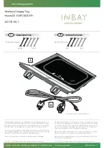
241170-53-1
Brand: Inbay Pages: 20

SunMax SM-SW-40
Brand: Ubiquiti Pages: 21

SPS 850
Brand: Patriot Pages: 8

WC303
Brand: Bekey Pages: 2

X-Peak Touch USB 2L
Brand: Jamara Pages: 8

SUNNY ISLAND SIC40-MPT
Brand: SMA Pages: 52

BC SMART 5000
Brand: BC BATTERY CONTROLLER Pages: 2

WPC15-1MWNA
Brand: Qi Pages: 5

Lewden ASPEN Series
Brand: Palazzoli Pages: 37

I-CHARGER 1.5
Brand: CEMONT Pages: 56

VELOX 1200T CD.2
Brand: CEMONT Pages: 82

HT608742
Brand: ABB Pages: 200

HT577406
Brand: ABB Pages: 132

HT594058
Brand: ABB Pages: 132

HT576380
Brand: ABB Pages: 132

HT576936
Brand: ABB Pages: 136


