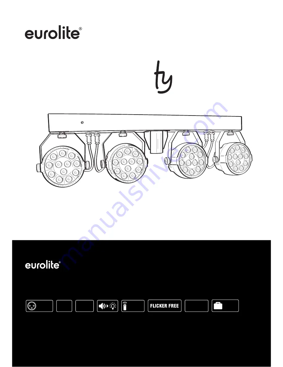
background image


Bedienungsanleitung
User Manual

LED KLS PARty Compact Light Set

Kompaktes LED-Scheinwerferset inklusive Transporttasche
Compact LED spotlight set including transport bag

No. 42110197

www.eurolite.de

MASTER

SLAVE

STAND
ALONE

REMOTE

CONTROL

DMX

RGBW

LED
KLS

Compact Light Set

PAR

BAG

Summary of Contents for LED KLS PARty

Page 1: ... PARty Compact Light Set Kompaktes LED Scheinwerferset inklusive Transporttasche Compact LED spotlight set including transport bag No 42110197 www eurolite de MASTER SLAVE STAND ALONE REMOTE CONTROL DMX RGBW LED KLS Compact Light Set PAR BAG ...

Page 2: ...00118185 Version 1 1 2 32 ...

Page 3: ...duct features 19 SAFETY INSTRUCTIONS 20 DESCRIPTION OF THE DEVICE 22 INSTALLATION 23 Fixing to a truss 23 Mounting on a speaker stand 23 CONNECTIONS 24 DMX512 control 24 Connection to the mains 24 Power supply of further devices 24 OPERATION 24 Stand alone mode 25 Remote control IR 30 26 DMX operation 27 CLEANING AND MAINTENANCE 30 Replacing the fuse 30 PROTECTING THE ENVIRONMENT 30 TECHNICAL SPEC...

Page 4: ...rieb Alle Personen die mit der Aufstellung Inbetriebnahme Bedienung Wartung und Instandhaltung dieses Gerätes zu tun haben müssen entsprechend qualifiziert sein diese Bedienungsanleitung genau beachten die Bedienungsanleitung als Teil des Produkts betrachten die Bedienungsanleitung während der Lebensdauer des Produkts behalten die Bedienungsanleitung an jeden nachfolgenden Besitzer oder Benutzer d...

Page 5: ...ion möglich 5 8 oder 20 DMX Kanäle wählbar Musiksteuerung über eingebautes Mikrofon Mikrofonempfindlichkeit einstellbar DMX512 Steuerung über jeden handelsüblichen DMX Controller möglich Per DMX kann jeder Spot einzeln angesteuert werden Zusätzliche Steuermöglichkeit über EUROLITE IR 30 Fernsteuerung im Lieferumfang enthalten Adressierung und Einstellungen über Steuereinheit mit 4 stelliger LED An...

Page 6: ...smäßig installierte Steckdose an deren Spannung und Frequenz mit dem Typenschild des Geräts genau übereinstimmt und die über einen Fehlerstromschutzschalter FI abgesichert ist Wenn der Netzstecker mit einem Schutzkontakt ausgestattet ist muss er an eine Steckdose mit Schutzleiter angeschlossen werden Deaktivieren Sie niemals den Schutzleiter eines Netzkabels Nichtbeachtung kann zu Schäden am Gerät...

Page 7: ...ften insbesondere die Bestimmungen der EN 60598 2 17 Versuchen Sie niemals die Installation selbst vorzunehmen wenn Sie nicht über eine ausreichende Qualifikation verfügen sondern beauftragen Sie einen professionellen Installateur Unsachgemäße Installationen können zu Verletzungen und oder zur Beschädigung von Eigentum führen Der Hersteller haftet nicht für Schäden die durch unsachgemäße Installat...

Page 8: ...R G B W 4 Anschlusskabel für die Steuereinheit 5 Stativhülse 6 Feststellschrauben 7 Sicherungshalter 8 Power IN 9 Power OUT 10 3 poliger DMX Eingang 11 3 poliger DMX Ausgang 12 Fangseilöse 13 LED Anzeige mit Bedientasten 14 Mikrofon 1 2 3 4 5 6 7 8 9 10 DMX IN DMX OUT POWER IN POWER OUT FUSE F1A 250V MENU UP DOWN ENTER MIC SAFETY ROPE 11 12 13 14 ...

Page 9: ... die Feststellschrauben fest 6 Sichern Sie das Gerät mit einem Fangseil oder einer anderen geeigneten Einrichtung zusätzlich ab Diese zweite Aufhängung muss auf Grundlage der aktuellsten Arbeitsschutzbestimmungen ausreichend dimensioniert und so angebracht sein dass im Fehlerfall der Hauptaufhängung kein Teil der Installation herabfallen kann Für die Befestigung eines Fangseils ist eine entspreche...

Page 10: ... Sie das beiliegende Netzkabel an und stecken den Netzstecker in eine geerdete Schutzkontaktsteckdose ein Damit ist das Gerät eingeschaltet 2 Zum Ausschalten ziehen Sie den Netzstecker aus der Steckdose 3 Schließen Sie das Gerät nicht über einen Dimmer an die Netzspannung an Für besseren Bedienkomfort verwenden Sie eine schaltbare Steckdose Stromversorgung von weiteren Geräten Über den Netzausgang...

Page 11: ...im Display die Anzeige A4 XX erscheint und drücken Sie die ENTER Taste 2 Stellen Sie mit den Tasten UP und DOWN die Nummer des gewünschten Programms ein A4 01 A4 03 3 Bestätigen Sie mit der Taste ENTER Das Menü für die Mikrofonempfindlichkeit wird aufgerufen 4 Stellen Sie mit den Tasten UP und DOWN die Mikrofonempfindlichkeit des Programms von A4 01 niedrig bis A4 09 hoch ein Bestätigen Sie mit de...

Page 12: ...swahl bei A1 Einstellung mit SPEED Ablaufgeschwindigkeit bei A2 A3 A5 A6 A7 Einstellung mit SEN Mikrofonempfindlichkeit Stufen 1 9 Einstellung mit Hinweise Die Fernbedienung wird mit eingesetzter Batterie geliefert Damit die Batterie während der Lagerung nicht entladen werden kann befindet sich eine Isolierfolie zwischen der Batterie und den Batteriekontakten Ziehen Sie vor dem ersten Betrieb die ...

Page 13: ...näle oder d 20 20 DMX Kanäle an Wählen Sie mit den Tasten UP und DOWN die gewünschte Anzahl der DMX Kanäle Bestätigen Sie mit der Taste ENTER 4 Wenn Daten empfangen werden blinkt der Punkt hinter der definierten Startadresse auf dem Display Werden keine Daten empfangen blinkt der Punkt nicht Hinweis Bitte vergewissern Sie sich dass sich die Steuerkanäle nicht mit anderen Geräten überlappen damit d...

Page 14: ...gramm 2 250 255 Musikgesteuertes Programm 3 8 Geschwindigkeit 000 255 Zunehmende Geschwindigkeit Siehe Grafik im Anschluss an das DMX Protokoll für Werte und Farbvoreinstellungen 20 Kanal Modus Kanal Wert Funktion 1 Dimmerintensität 000 255 Allmähliche Einstellung der Dimmerintensität 0 100 2 Strobe 000 009 Keine Funktion 010 255 Strobeeffekt mit zunehmender Geschwindigkeit 3 Rot 000 255 Zunehmend...

Page 15: ...Intensität der weißen LEDs 0 100 19 Interne Programme 000 009 Keine Funktion 010 099 Farbvoreinstellungen 100 129 Farbwechsel 130 159 Farbüberblendung 160 189 Lauflicht 190 219 Musikgesteuertes Programm 1 220 249 Musikgesteuertes Programm 2 250 255 Musikgesteuertes Programm 3 20 Geschwindigkeit 000 255 Zunehmende Geschwindigkeit Werte und Farbvoreinstellungen für Kanal 7 im 8 Kanal Modus und Kanal...

Page 16: ...erung des Geräts defekt ist ersetzen Sie diese durch eine Sicherung gleichen Typs 1 Trennen Sie das Gerät vom Netz und lassen Sie es abkühlen 2 Öffnen Sie den Sicherungshalter am Netzanschluss mit einem passenden Schraubendreher 3 Entfernen Sie die defekte Sicherung aus dem Sicherungshalter und setzen Sie die neue Sicherung ein 4 Setzen Sie den Sicherungshalter wieder im Gehäuse ein Danach kann da...

Page 17: ...zu entflammbaren Oberflächen 0 5 m Mindestabstand zum angestrahlten Objekt 0 3 m Zubehör EUROLITE DMX LED Color Chief Controller Best Nr 70064575 OMNITRONIC BS 1 EU Boxenhochständer Best Nr 60004160 EUROLITE DMX Kabel XLR 3pol 3m schwarz Best Nr 3022785H PSSO DMX Kabel XLR 3pol 3m schwarz Neutrik Best Nr 30227810 OMNITRONIC Kaltgeräte Verlängerung 3x1 0 3m schwarz Best Nr 30235201 EUROLITE IR 30 F...

Page 18: ...n for the correct use of the product Every person involved with the installation operation and maintenance of this device has to be qualified follow the instructions of this manual consider this manual to be part of the total product keep this manual for the entire service life of the product pass this manual on to every further owner or user of the product download the latest version of the user ...

Page 19: ...ster Slave function 5 8 or 20 DMX channels selectable Sound control via built in microphone microphone sensitivity adjustable DMX512 control via standard DMX controller Via DMX each spot can be controlled individually Additional controlling possibility via the EUROLITE IR 30 remote control included in delivery Addressing and setting via control panel with 4 digit LED display Functions RGBW color m...

Page 20: ...so could result in damage to the device and possibly injure the user The mains outlet must be easily accessible so that you can unplug the device quickly if need be Never touch the mains plug with wet or damp hands There is the risk of potentially fatal electric shock The mains cable must not be bent or squeezed Keep it away from hot surfaces or sharp edges Never pull the mains cable to disconnect...

Page 21: ...ot be made liable for damages caused by incorrect installations or insufficient safety precautions For overhead use always secure the device with a secondary safety attachment such as a safety bond or safety net Make sure that the area below the installation place is blocked when rigging derigging or servicing the device For commercial use the country specific accident prevention regulations of th...

Page 22: ...s R G B W each 4 Connection cable for the control unit 5 Stand sleeve 6 Fixation screws 7 Fuseholder 8 Power IN 9 Power OUT 10 3 pin DMX IN 11 3 pin DMX OUT 12 Safety eyelet 13 LED display with operating buttons 14 Microphone 1 2 3 4 5 6 7 8 9 10 DMX IN DMX OUT POWER IN POWER OUT FUSE F1A 250V MENU UP DOWN ENTER MIC SAFETY ROPE 11 12 13 14 ...

Page 23: ...d the TPC hooks in the truss and tighten the fixation screws 6 Secure the device with a safety bond or other secondary attachment This secondary safety attachment must be sufficiently dimensioned in accordance with the latest industrial safety regulations and constructed in a way that no part of the installation can fall down if the main attachment fails An appropriate eyelet is mounted on the dev...

Page 24: ...0 volts 1 Connect the device via the enclosed mains cable to a grounded mains socket Thus the unit is switched on 2 To switch off the unit disconnect the power plug 3 Do not connect the unit to the mains voltage via a dimmer For a more convenient operation use a mains outlet which is switchable Power supply of further devices The jack POWER OUT allows for power supply of further devices To interco...

Page 25: ...nd control 1 Press the button MENU so many times until A4 XX appears on the display and confirm with ENTER 2 Use the buttons UP and DOWN to select the number of the desired program A4 01 A4 03 3 Confirm with the ENTER button The display indicates menu item microphone sensitivity 4 Use the buttons UP and DOWN to adjust the microphone sensitivity of the program from A4 01 low to A4 09 high Confirm w...

Page 26: ...ting via SEN Microphone sensitivity Levels 1 9 Setting via Notes The remote control is supplied with a battery inserted An insulating foil between the battery and the battery contacts prevents the battery from being discharged during storage Prior to the first operation remove the foil from the battery support on the rear side of the remote control Otherwise operation of the remote control is not ...

Page 27: ... the desired starting address will flash If there is no data received the dot will not flash Note Please make sure that you do not have any overlapping channels in order to control each device correctly and independently from any other fixture on the DMX chain If several devices are addressed similarly they will work synchronically DMX protocol 5 Channel Mode Channel Value Function 1 Dimmer intens...

Page 28: ...100 5 Blue 000 255 Increasing intensity of the blue LEDs 0 100 6 White 000 255 Increasing intensity of the white LEDs 0 100 7 Red 000 255 Increasing intensity of the red LEDs 0 100 Spot 2 8 Green 000 255 Increasing intensity of the green LEDs 0 100 9 Blue 000 255 Increasing intensity of the blue LEDs 0 100 10 White 000 255 Increasing intensity of the white LEDs 0 100 11 Red 000 255 Increasing inte...

Page 29: ...Sound controlled program 3 20 Speed 000 255 Increasing speed Values and Preset colors for channel 7 in 8 channel mode and channel 19 in 20 channel mode 010 015 All colors 058 063 Red Green Blue 016 021 Red 064 069 Red White 022 027 Green 070 075 White Green 028 033 Blue 076 081 White Blue 034 039 White 082 087 White Red Green 040 045 Red Green 088 093 White Green Blue 046 051 Green Blue 094 099 Wh...

Page 30: ...use by a fuse of same type and rating 1 Disconnect the device from power and allow it to cool 2 Open the fuse holder of the mains connection with a fitting screwdriver 3 Remove the old fuse from the fuse holder and replace it with a new fuse 4 Carefully push the fuse holder back into its position before reapplying power PROTECTING THE ENVIRONMENT Disposal of old equipment When to be definitively p...

Page 31: ...temperature TC 70 C Min distance from flammable surfaces 0 5 m Min distance to lighted object 0 3 m Accessories EUROLITE DMX LED Color Chief Controller No 70064575 OMNITRONIC BS 1 EU Loudspeaker Stand No 60004160 EUROLITE DMX cable XLR 3pin 3m black No 3022785H PSSO DMX cable XLR 3pin 3m black Neutrik No 30227810 OMNITRONIC IEC Extension 3x1 0 3m black No 30235201 EUROLITE IR 30 Remote Control No ...

Page 32: ...Eurolite is a brand of Steinigke Showtechnic GmbH Andreas Bauer Str 5 97297 Waldbüttelbrunn Germany D00118185 Version 1 1 Publ 07 12 2018 ...

Reviews: