1
of 5
© 2015 TE Connectivity family of companies
All Rights Reserved
*Trademark
TE Connectivity, TE connectivity (logo), and TE (logo) are trademarks. Other logos, product, and/or company names may be trademarks of their respective owners.
PRODUCT INFORMATION 1-800-522-6752
This controlled document is subject to change.
For latest revision and Regional Customer Service,
visit our website at
www.te.com
.
Instruction Sheet
408-10243
02 JUL 15
Rev E
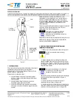
Figure 1
1.
INTRODUCTION
This instruction sheet provides information on the application and maintenance procedures for the SDE
PEW-12 Hand Crimping Tool 2031734-1. This tool consists of Hand Tool Frame Assembly 9-1478240-0
(Instruction Sheet
408-8851
), and die assembly 2031734-2. See Figure 1.
NOTE
Dimensions in this instruction sheet are in millimeters with [inches in brackets]. Figures and illustrations are for reference only
and are not drawn to scale.
2.
DESCRIPTION
The die assembly is designed with two crimp nests to terminate the RJ Point Five* Plug Kit 2007312-1 utilizing
a shell crimp (scroll crimp), and a contact piercing crimp. This document only deals with the termination
procedures. Complete assembly procedures for the plug kit may be found in Application Specification
114-13235
.
3.
INSTALLATION AND REMOVAL OF DIE SET AND LOCATOR ASSEMBLY
1. Open the tool handles and remove the two die retaining screws from the tool jaws.
2. Place the wire anvil so that the chamfered side and the marked surfaces face outward, when mounted
in the moving jaw of the tool frame.
3. Insert the short die retaining screw through the jaw and through the anvil die, and tighten the screw
just enough to hold the die in place. Do not tighten the screw completely at this time.
4. Place the wire crimper so that the chamfered side and the marked surface face outward, when
mounted in the stationary jaw of the tool frame.
5. Insert the long die retaining screw through the jaw and through the crimper die, and tighten the screw
just enough to hold the die in place. Do not tighten the screw completely at this time.
6. Carefully close the tool handles, making sure that the anvil and crimper align properly. Continue
closing the tool handles until the ratchet in the tool frame has engaged sufficiently to hold the anvil and
crimper in place, then tighten both die retaining screws.
PROPER USE GUIDELINES
Cumulative Trauma Disorders can result from the prolonged use of manually powered hand tools. Hand tools are intended for occasional use and low
volume applications. A wide selection of powered application equipment for extended-use, production operations is available.
SDE PEW-12 Hand Crimping
Tool Assembly 2031734-1 with
Die Assembly 2031734-2
SDE PEW-12 Hand
Crimping Tool 2031734-1
Die Assembly
2031734-2
Hand Tool Frame
Assembly 9-1478240-0
Ratchet Adjustment
Wheel
OR
IGIN
A
L
IN
STR
U
C
TION
S