Ericsson Base Station F800, Руководство по обслуживанию на месте
"Ericsson Base Station F800 - высококачественное оборудование для сотовой связи. Получите полное понимание работы устройства с помощью Field Service Manual. Скачайте бесплатно руководство по эксплуатации на manualshive.com. Максимально эффективное использование продукта с помощью подробной инструкции."
Поделиться
Скачать


Отзывы:
Нет отзывов
Похожие инструкции для Base Station F800

TBR7
Бренд: Tao Motor Страницы: 3

WorkCentre 7132
Бренд: Xerox Страницы: 3

QR545
Бренд: Allen Sports Страницы: 2

Fireplace Surrounds None
Бренд: Dimplex Страницы: 2

0355 02
Бренд: Gira Страницы: 10

JB21UNISTY
Бренд: J.Burrows Страницы: 4

RBC53
Бренд: Tripp Lite Страницы: 2

UNI-UPRS
Бренд: Victory 4x4 Страницы: 13

32 025 888
Бренд: Saab Страницы: 3

ECC0310R
Бренд: R&G Страницы: 8
99944200890
Бренд: Echo Страницы: 84

Micropulse BTL5 Series
Бренд: Balluff Страницы: 94

VA0916012
Бренд: Hoffman Страницы: 2

DASH FM
Бренд: Burley Страницы: 84
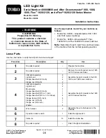
04063
Бренд: Toro Страницы: 16

M-TRACK 2X2
Бренд: M-Audio Страницы: 20

3N1-PJT
Бренд: Omnimount Страницы: 28

Pasport PS-2111
Бренд: PASCO Страницы: 4


