background image

Form No. 3415-336 Rev A
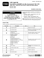
LED Light Kit

Serial Number 400000000 and After Greensmaster

®

800, 1000,

1600, Flex

1820/2120, and eFlex

®

1820/2120 Series Mower

Model No. 04063

Model No. 04064

Installation Instructions

WARNING

CALIFORNIA

Proposition 65 Warning

This product contains a chemical

or chemicals known to the State of

California to cause cancer, birth defects,

or reproductive harm.

Use the appropriate model for your machine as
follows:

Model No. 04063—Greensmaster

®

800, 1000,

and 1600 series machines

Model No. 04064—Greensmaster

®

Flex

1820/2120 or eFlex 1820/2120 series machines

Note:

Determine the left, right, front, and back sides

of the machine from the normal operating position.

Loose Parts

Use the chart below to verify that all parts have been shipped.

Procedure

Description

Qty.

Use

1

No parts required

Prepare the machine.

2

No parts required

Remove the control-panel cover (1820
or 2120 series machines).

LED light assembly

2

Light mount

2

Flange-head bolt (3/8 inch)

4

3

Flange nut (3/8 inch)

2

Assemble the light mounts to the 800,
1000, and 1600 series machine.

LED light assembly

2

Light mount

2

Mount plate

1

Flange-head bolt (3/8 inch)

1

Flange-head bolt (5/16 x 1 inch)

1

Flange-head bolt (5/16 x 1-1/2 inches)

4

Flange locknut (5/16 inch)

4

Flange nut (3/8 inch)

1

Flange nut (5/16 inch)

1

4

Washer

4

Assemble the light mounts to the 1820
or 2120 series machine.

5

Wire harness

2

Assemble the wire harnesses to the
machine.

6

2-position rocker switch

1

Install the light switch.

7

Cable tie

10

Install the cable ties.

8

No parts required

Finish the light kit installation.

© 2017—The Toro® Company
8111 Lyndale Avenue South
Bloomington, MN 55420

Register at www.Toro.com.

Original Instructions (EN)

Printed in the USA

All Rights Reserved

*3415-336* A


Summary of Contents for 04063

Page 1: ...cription Qty Use 1 No parts required Prepare the machine 2 No parts required Remove the control panel cover 1820 or 2120 series machines LED light assembly 2 Light mount 2 Flange head bolt 3 8 inch 4...

Page 2: ...ion refer to the Operator s Manual 3 Set the throttle control to the SLOW position and push the On Off switch to the OFF position refer to the Operator s Manual 4 Pull the service brake lever back and...

Page 3: ...tain the flange head screws and control panel cover for assembly in Installing the Control Panel Cover page 14 3 Assembling the Light Mounts to the 800 1000 and 1600 Series Machine Parts needed for th...

Page 4: ...re the LED lights to each light mount Figure 7 g200656 Figure 7 1 LED light 3 Washer 2 Light mount 4 Nut 4 Assembling the Light Mounts to the 1820 or 2120 Series Machine Parts needed for this procedur...

Page 5: ...hown 1 Flange locknut 5 16 inch 4 Flange head bolt 5 16 x 1 1 2 inches 2 Mount plate 5 Left side plate 3 Washer g200371 Figure 9 Flex eFlex 2120 Machine Shown 1 Flange locknut 5 16 inch 4 Flange head...

Page 6: ...rs and 2 flange nuts 5 16 inch to secure a light mount to the right drive housing Figure 11 g206121 Figure 11 1 Flange head bolt 5 16 x 1 1 2 inch 4 Light mount 2 Washer 5 Flange locknut 5 16 inch 3 D...

Page 7: ...together securely g200657 Figure 13 1 2 socket connector wire harness 2 2 pin connector LED light 2 Repeat step 1 for the other wire harness and LED light Routing the Wire Harness Route the wire harn...

Page 8: ...shown 1 2 socket connector wire harness machine 3 2 pin connector wire harness LED light kit 2 Plug 4 Console 2 Connect the 2 pin connector of the LED light wire harness to the 2 socket connector of...

Page 9: ...re 18 Left side of the machine shown 1 2 pin connector wire harness LED light kit 3 2 socket connector wire harness machine 2 Plug 2 Connect the 2 pin connector of the LED light wire harness to the 2...

Page 10: ...re 20 Left side of the machine shown 1 2 pin connector wire harness LED light kit 3 2 socket connector wire harness machine 2 Plug 2 Connect the 2 pin connector of the LED light wire harness to the 2...

Page 11: ...ne wire harness through the opening in the control panel Figure 22 4 Connect the 10 pin connector of the 2 position rocker switch into the 10 socket connector of the wire harness for the machine Figur...

Page 12: ...n rocker switch 2 Opening control panel 4 8 socket connector wire harness LED light and wireless hour meter harness kit 2 Pull up the 8 socket connector of the wire harness for the machine through the...

Page 13: ...ies ensure that the wire harnesses have enough slack to prevent stress points and are free from any moving parts 1 Use 8 cable ties to secure the wire harnesses to the machine Figure 27 Note Attach 4...

Page 14: ...e Light Kit Installation No Parts Required Installing the Control Panel Cover 1820 or 2120 Series Machines 1 Align the keyhole slot in the control panel cover over the traction and reel drive handle F...

Page 15: ...the battery wire harness refer to Figure 2 of Disconnecting the Battery page 2 Operation Operating the Light Switch Press the rocker switch to turn the LED lights to the ON or OFF position refer to F...

Page 16: ......

Reviews: