background image

Products

Solutions

Services

4900002256 Rev B

Hardware Installation and Maintenance Manual

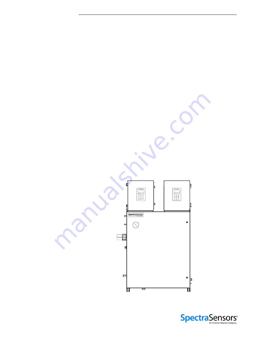
2-Pack Analyzer System

Class I, Division 2, Grp. B, C and D, T3/T3C IP66

Class I, Zone 2 IIB+H2 T3/T3C IP66

Copyright © 2021 SpectraSensors, Inc. No part of this manual may be reproduced in 

whole or in part without the express written permission of SpectraSensors, Inc. 

SpectraSensors reserves the right to change product design and specifications at any 

time without prior notice.

.

.

Summary of Contents for SS1000

Page 1: ...n 2 Grp B C and D T3 T3C IP66 Class I Zone 2 IIB H2 T3 T3C IP66 Copyright 2021 SpectraSensors Inc No part of this manual may be reproduced in whole or in part without the express written permission of SpectraSensors Inc SpectraSensors reserves the right to change product design and specifications at any time without prior notice ...

Page 2: ......

Page 3: ...a SS2100i 1 SS2100i 2 Not used Used for differential analyzers Used for non differential analyzers 2 Pack 3 Pack Used on right side analyzer electronics Used on left side analyzer electronics Not used SS1000 SS500 SS500e SS500XP SS2000 SS2000e SS2000XP SS3000 SS3000e Used Not used Not used ...

Page 4: ......

Page 5: ...uld be Included in the Shipping Box 3 1 Lifting Carrying the Analyzer 3 1 Inspecting the Analyzer 3 2 Mounting and Installing the Analyzer 3 3 Hardware and tools for mounting and installation 3 3 Hardware 3 3 Tools 3 3 To mount the analyzer 3 4 Connecting Electrical Power to the Analyzer 3 4 Protective chassis and ground connections 3 5 To connect electrical power to Analyzer A 3 6 Field interface...

Page 6: ...isolate the SCS for short term shutdown 4 8 To isolate the process sample tap for long term shutdown 4 9 To purge for shipment relocation 4 11 Heat Trace Bundle Sleeve Optional 4 11 Removing the heat trace bundle 4 11 Appendix A Specifications Spare Parts A 14 Appendix B Maintenance and Troubleshooting Gas Leaks B 1 Contamination B 1 Excessive Sampling Gas Temperatures and Pressures B 2 Electrical...

Page 7: ...sal of Used Scrubbers B 26 Instrument Issues B 26 Packing B 30 To prepare the analyzer for shipment or storage B 30 Storage B 31 Service Contact B 31 Before contacting Service B 31 Service repair order B 32 Renewity returns B 32 Disclaimers B 32 Warranty B 32 Index Index 1 ...

Page 8: ...2 Pack Analyzer System iv 4900002256 rev B 4 13 21 THIS PAGE INTENTIONALLY LEFT BLANK ...

Page 9: ...s control board terminal block in the Analyzer A electronics enclosure 3 7 Figure 3 3 AC and DC connections for the electronics control board terminal block in the Analyzer B electronics enclosure 3 8 Figure 3 4 AC connection terminal block for enclosure heater 3 9 Figure 3 5 Applying conduit lubricant 3 11 Figure 3 6 Analyzer A mating terminal block TB2 for connecting signal cables 3 13 Figure 3 ...

Page 10: ...or B 12 Figure B 7 Removing excess seal tape from flange B 12 Figure B 8 Removing excess seal tape from inside cell B 13 Figure B 9 Replacing seal tape B 13 Figure B 10 Replacing pressure sensor B 14 Figure B 11 New pressure sensor installed B 14 Figure B 12 Removed 0 8 m measurement cell with pressure sensor face up B 16 Figure B 13 Removing the old pressure sensor B 16 Figure B 14 Removing exces...

Page 11: ... Table 3 1 Analyzer A input output signal connections 3 14 Table 3 2 Analyzer B input output signal connections 3 16 Table A 1 2 Pack Analyzer A H2S Analyzer B CO2 specifications A 1 Table A 2 2 Pack Analyzer A H2S Analyzer B H2O specifications A 3 Table A 3 Replacement parts for 2 Pack analyzer A 14 Table B 1 Potential analyzer issues and solutions B 26 ...

Page 12: ...2 Pack Analyzer System viii 4900002256 rev B 4 13 21 THIS PAGE INTENTIONALLY LEFT BLANK ...

Page 13: ...reading the Table of Contents There are a number of options and accessories available for the 2 Pack analyzer system This manual has been written to address the most common options and accessories Images tables and charts have been included to provide a visual understanding of the analyzers and its functions Special symbols are also used to provide the user with key information regarding the syste...

Page 14: ... carefully controlled to avoid creating any possible ignition sources e g heat arcing sparking etc Toxins SpectraSensors analyzers measure a variety of gases including high level H2S Follow all safety protocols governing toxic gases and potential leaks Inhalation Inhaling toxic gases or fumes may cause physical harm or death Technicians are expected to follow all safety protocols established by th...

Page 15: ...ions for the fuse closest to label PROTECTIVE EARTH GROUND Symbol indicates the connection point of the ground wire from the main power source FUNCTIONAL EARTH GROUND Symbol indicates grounding points intended primarily for troubleshooting INVISIBLE LASER RADIATION Avoid exposure to beam Class 3b Radiation Product Refer servicing to the manufacturer or qualified personnel Removing label from measu...

Page 16: ...ensors was acquired by the Endress Hauser Group in 2012 Manufacturer Address SpectraSensors Inc An Endress Hauser Company 11027 Arrow Route Rancho Cucamonga CA 91730 United States www spectrasensors com General notes and important information concerning the installation and operation of the analyzer Failure to follow all directions may result in fire INVISIBLE LASER RADIATION Avoid exposure to bea...

Page 17: ...CS has been included with the analyzer The SCS has been specifically designed to deliver an optimum sample stream that is representative of the process systems stream at the time of sampling Most 2 Pack analyzer systems are configured for use at extractive natural gas sampling stations How the Analyzers Work The 2 Pack analyzer system employs tunable diode laser absorption spectro scopy TDLAS to d...

Page 18: ...ion by the trace gas with absorption cross section According to the Beer Lambert absorption law the intensity remaining I as measured by the detector at the end of the beam path of length cell length x number of passes is given by 1 where N represents the species concentration Thus the ratio of the absorption measured when the laser is tuned on resonance versus off resonance is directly proportion...

Page 19: ... slope of raw data results from ramping the current to tune the laser which not only increases the wavelength with current but also causes the corresponding output power to increase By normalizing the signal by the incident intensity any laser output fluctuations are canceled and a typical yet more pronounced absorption profile results Refer to Figure 1 3 on page 1 8 3 0 2 5 2 0 1 5 1 0 0 5 Incide...

Page 20: ...er is a spectrum of the pure analyte This technology is used for very low or trace measurements and is also useful when the background matrix changes over time Refer to http www spectrasensors com spectral subtraction in tdlas analysis for more information Wavelength modulation spectroscopy WMS signal detection SpectraSensors takes the fundamental absorption spectroscopy concept a step further by ...

Page 21: ...ous mixed hydrocarbon background streams is accomplished by selecting a different optimum diode laser wavelength between 700 nm to 3000 nm which provides the least amount of sensitivity to background stream variations Getting to Know the Analyzer Figure 1 5 on page 1 10 shows a 2 Pack analyzer from the front view The analyzer is comprised of three main enclosures the two analyzer electronics enclo...

Page 22: ...rument air are connected on the sides of the SCS enclosure Inside the analyzer electronics enclosure is the electronics assembly as shown in Figure 1 6 on page 1 11 Figure 1 7 on page 1 12 Figure 1 8 on page 1 13 and Figure 1 9 on page 1 14 Figure 1 5 2 Pack analyzer architecture SIGNAL WIRING ANALYZER POWER ANALYZER A ELECTRONICS ENCLOSURE INSTRUMENT AIR INLET OPTIONAL VAL GAS INLET OPTIONAL SAMP...

Page 23: ...BLE ALARM GENERAL FAULT ALARM CUSTOMER GROUND AC POWER SUPPLY BACKPLANE ARM9 CONTROL BOARD STACK COMPONENT GROUND HYTEK TEMPERATURE CONTROLLER TERMINAL BLOCK TB3 INTERNAL PRESSURE TEMPERATURE ALARM SIGNAL RELAYS PROTECTIVE GROUND Figure 1 6 Analyzer A ARM9 electronics control board AC showing signal terminal block and alarm relays SIGNAL CONVERTER RS 232 TO RS 485 OPTIONAL ...

Page 24: ...LARM GENERAL FAULT ALARM CUSTOMER GROUND DC POWER SUPPLY BACKPLANE ARM9 CONTROL BOARD STACK COMPONENT GROUND HYTEK TEMPERATURE CONTOLLER TERMINAL BLOCK TB3 INTERNAL PRESSURE TEMPERATURE ALARM SIGNAL RELAYS PROTECTIVE GROUND Figure 1 7 Analyzer A ARM9 electronics control board DC showing signal terminal block and alarm relays SIGNAL CONVERTER RS 232 TO RS 485 OPTIONAL 24 V ...

Page 25: ...aintenance Manual 1 13 Figure 1 8 Analyzer B HC12 electronics control board AC showing signal terminal block and alarm relays 4 20 mA BOARDS SIGNAL CONVERTER RS 232 TO ETHERNET COMMON NO NC FUSE F4 ASSIGNABLE ALARM GENERAL FAULT ALARM SIGNALS ...

Page 26: ...ystem 1 14 4900002256 rev B 4 13 21 Figure 1 9 Analyzer B HC12 electronics control board DC showing signal terminal block and alarm relays 4 20 mA BOARDS COMMON NO NC FUSE F5 ASSIGNABLE ALARM GENERAL FAULT ALARM SIGNALS ...

Page 27: ...zer A Drawing Reference Voltage Description Rating Figure 1 6 F1 120 VAC 1 Solenoid Miniature Fuse 5 x 20 mm Time Delay 250 VAC 0 25 A 2 Solenoids Miniature Fuse 5 x 20 mm Time Delay 250 VAC 0 4 A 3 Solenoids Miniature Fuse 5 x 20 mm Time Delay 250 VAC 0 4 A F2 Miniature Fuse 5 x 20 mm Time Delay 250 VAC 0 8 A F1 240 VAC 1 Solenoid Miniature Fuse 5 x 20 mm Time Delay 250 VAC 0 125 A 2 Solenoids Mi...

Page 28: ...pecifications Analyzer B Drawing Reference Voltage Description Rating Figure 1 8 F4 120 VAC Miniature Fuse 5 x 20 mm Time Delay 250 VAC 0 8 A 240 VAC Miniature Fuse 5 x 20 mm Time Delay 250 VAC 0 8 A Figure 1 9 F5 24 VDC Miniature Fuse 5 x 20 mm Time Delay 250 VAC 1 6 A ...

Page 29: ...ng any part of the sample system Exposure to toxic gas H2S Follow the procedure below if there has been any suspected leak from the sample system and accumulated Sample Conditioning System SCS enclosure 1 Purge the SCS enclosure to remove any potentially toxic gas 2 Test the H2S levels of the SCS enclosure using the port from the safety purge kit to ensure the purge has cleared any toxic gas 3 If ...

Page 30: ...ces e g heat arcing sparking etc All tools must be appropriate for the area and hazards present Electrical connections must not be made or broken with power applied to avoid arcing Complete this action before performing any service that requires working near the main input power or disconnecting any wiring or other electrical components Note any live electrical components and avoid any contact wit...

Page 31: ...d weight configurations can weigh approximately 86 Kg 190 lbs SpectraSensors recommends the use of a forklift pallet jack etc to lift and or move the analyzer If the analyzer is to be lifted by hand designate multiple individuals and distribute the weight among personnel to avoid injury Never lift the analyzer by the electronics enclosure Always carry the load using one of the following points met...

Page 32: ...m configured with various accessories and options Contact Service if there is any discrepancy with the order refer to Service Contact on page B 31 Ensure all equipment used for lifting moving the analyzer is rated for the weight load Avoid jolting the instrument by dropping it or banging it against a hard surface which may disturb the optical alignment Figure 3 1 Lifting points and mounting dimens...

Page 33: ...and tools for mounting and installation Depending on the particular configuration of accessories and options ordered you may need the following hardware and tools to complete the installation process Hardware Mounting hardware e g 3 8 in x 1 1 2 in machine screws and nuts Stainless steel tubing SpectraSensors recommends using 1 4 in O D x 0 035 in wall thickness seamless stainless steel tubing 3 4...

Page 34: ...n your analyzer system will be set up for 120 VAC or 240 VAC at 50 60 Hz single phase input or optional 24 VDC input Check the rating label to determine the power input requirements All work must be performed by qualified personnel Conduit seals should be used where appropriate in compliance with local regulations When mounting the analyzer be sure not to position the instrument so that it is diff...

Page 35: ...t must use the green yellow color Refer to Figure 1 5 on page 1 10 for the chassis ground location and Figure 1 6 on page 1 11 and Figure 1 7 on page 1 12 for the protective ground location Interconnection of the analyzer enclosure and cell enclosure shall be accomplished using wiring methods approved for Class 1 Division 2 hazardous locations as per the Canadian Electrical Code CEC Appendix J and...

Page 36: ...erminal marked NEU and the hot wire to the terminal marked L1 as shown in Figure 3 2 on page 3 7 Connect the ground wire to the safety ground terminal marked with the symbol For DC systems connect the minus wire to the terminal marked and the plus wire to the terminal marked as shown in Figure 3 2 on page 3 7 7 Close and tighten the Analyzer A electronics enclosure door Hazardous voltage and risk ...

Page 37: ...stems pull ground neutral and hot wires 14 AWG minimum into the electronics enclosure For DC systems pull the ground plus and minus wires Connecting power to L1 also powers the solenoids if included Hazardous voltage and risk of electric shock Failure to properly ground the analyzer may create a high voltage shock hazard Conduit seals should be used where appropriate in compliance with local regul...

Page 38: ...w 6 Connect the ground wire to the ground terminal marked 7 Close and tighten the Analyzer B electronics enclosure door Because the breaker in the power distribution panel or switch will be the primary means of disconnecting the power from the analyzer the power distribution panel should be located in close proximity to the equipment and within easy reach of the operator or within 10 feet of the a...

Page 39: ... the bottom right of the sample conditioning system SCS enclosure refer to Figure 1 5 on page 1 10 To connect electrical power to the enclosure heater 1 Open the heated SCS enclosure door Take care not to disturb anything inside 2 Open the power terminal box inside the heated SCS enclosure as shown in Figure 3 4 below The black white brown and green wires in are shown for reference Hazardous volta...

Page 40: ...n SpectraSensors recommends using STL8 screw thread lubricant or equivalent on all conduit screw thread and its taped opening STL8 Screw Thread Lubricant is a lithium based anti galling substance with excellent adhesion that maintains rain tightness and grounding continuity between conduit fittings This lubricant has proven very effective between parts made of dissimilar metals and is stable in te...

Page 41: ...espective analyzer electronics enclosures as shown in Figure 1 6 on page 1 11 and Figure 1 7 on page 1 12 Analyzer A or Figure 1 8 on page 1 13 and Figure 1 9 on page 1 14 Analyzer B By default the 4 20 mA current loop outputs are factory set to source current Eyes May cause minor irritation Skin May cause minor irritation Ingestion Relatively non toxic Ingestion may result in a laxative effect In...

Page 42: ...ndix A To connect Analyzer A signal and alarm cables 1 Disconnect power from analyzer and open the Analyzer A electronics enclosure cover Take care not to disturb the electrical assembly inside 2 Run conduit from the signal alarm receiving station to the conduit hub in the upper left hand corner of the Analyzer A electronics enclosure labeled for signal input output Refer to Application of conduit...

Page 43: ...ock into its base and verify that each connection is secure 8 Strip back the jacket and insulation of the alarm cables just enough to connect to the alarm relays shown in Figure 1 6 on page 1 11 or Figure 1 7 on page 1 12 9 Connect the cable for the General Fault Alarm to the common and NO terminals on the corresponding relays shown in Figure 1 6 on page 1 11 or Figure 1 7 on page 1 12 10 Connect ...

Page 44: ...the upper right hand corner of the Analyzer B electronics enclosure Refer to Application of conduit lubricant on page 3 10 and analyzer drawings in Appendix A Table 3 1 Analyzer A input output signal connections Terminal Description D Conn Color 1 Analyzer A Serial RX Pin 3 Black 2 Analyzer A Serial TX Pin 2 Red 3 COM Serial Ground Pin 5 Shield 4 N C 5 N C 6 N C 7 Analyzer A Current Loop 8 Analyze...

Page 45: ...ng a nine pin Sub D connector for connection to a computer serial port 7 Re insert the mating terminal block into its base and verify that each connection is secure 8 Strip back the jacket and insulation of the alarm cables just enough to connect to the alarm relays shown in Figure 1 8 on page 13 or Figure 1 9 on page 1 14 9 Connect the cable for each General Fault Alarm to the common and NO termi...

Page 46: ... qualified in electronics assembly Table 3 2 Analyzer B input output signal connections Terminal Description D Connector Color 1 Analyzer A Serial RX Pin 3 Black 2 Analyzer A Serial TX Pin 2 Red 3 Analyzer A Serial Ground Pin 5 Shield 4 Analyzer B Serial RX Pin 3 Black 5 Analyzer B Serial TX Pin 2 Red 6 Analyzer B Serial Ground Pin 5 Shield 7 Analyzer A Current Loop 8 Analyzer A Current Loop 9 Ana...

Page 47: ... 13 or Figure 1 9 on page 1 14 Analyzer B 3 Remove the jumper JMP1 shown in Figure 3 8 on page 3 17 connecting the center pin to point A 4 For 4 20 mA sink carefully replace the jumper to connect the center hole with point P 5 Reconnect power to the analyzer Confirm the 4 mA minimum and 20 mA maximum points 6 Close and tighten the analyzer electronics enclosure cover Needle nose pliers may be requ...

Page 48: ...ressed c Set 4 20 mA Test 100 this displays the 20 mA on the AO circuit when 5 is pressed 5 Press and 1 to return to Normal Mode To calibrate the analog output Analyzer B 1 Connect a calibrator and digital multi meter into the circuit 2 On the analyzer keypad press 2 Mode 2 the password 3142 and 3 Continue pressing the key until the 4 20 mA Test parameter displays 4 Set the current loop output to ...

Page 49: ...eters on the end of the board to change the zero and span readings Refer to Figure 3 8 on page 3 17 3 Press and 1 to return to Normal Mode For more information on the analyzer programming refer to the Firmware Operator s Manual Ethernet connection Optional Refer to the appropriate Firmware for setting up the optional Ethernet connection if installed Connecting the Gas Lines Once you have verified ...

Page 50: ...tainless steel tubing rated for the specified supply pressure shown in Appendix A Run the tubing from each field pressure reducing station to the corresponding sample supply port of the SCS 6 Bend tubing using industrial grade benders check tubing fit to ensure proper seating between the tubing and fittings 7 Fully ream all tubing ends Blow out the lines for 10 to 15 seconds with clean dry nitroge...

Page 51: ...air prior to making the connection 4 Connect the sample bypass return tube to the SCS using the 1 4 in stainless steel compression type fittings provided 5 Tighten all new fittings 1 1 4 turns with a wrench from finger tight For connections with previously swaged ferrules thread the nut to the previously pulled up position then tighten slightly with a wrench Secure tubing to appropriate structural...

Page 52: ... with a wrench from finger tight a For connections with previously swaged ferrules thread the nut to the previously pulled up position then tighten slightly with a wrench Secure tubing to appropriate structural supports as required 7 Check all connections for gas leaks SpectraSensors recommends using a liquid leak detector Connecting the Validation Gas Source if Applicable For systems with validat...

Page 53: ... source valve to the vent or return should be conditioned by flowing sample gas through the system for up to 12 hours or until the reading stabilizes after the system is powered up and before actual readings are taken Progress of the system conditioning can be monitored via the gas concentration readings Once the gas constituents have reached equilibrium with the system walls the readings should s...

Page 54: ...ble cutter Use the following instructions to install this seal 1 From the inside of the enclosure place the rigid plastic nylon threaded nut through the access hole to the exterior so that the nut flanged end is up against the inside of the enclosure 2 From the outside place the O ring over the nut threaded end and position against the enclosure 3 Screw the shrinkable internally threaded nose onto...

Page 55: ...ign operation or maintenance of the SCS refer to Service Contact on page B 31 About the SCS SpectraSensors SCS is designed to filter incoming gas as well as control pressure and flow to the analyzer The SCS uses a 7 micron particulate filter and a membrane separator that removes entrained liquids or particles from the natural gas stream before they enter the analyzer Because SpectraSensors analyze...

Page 56: ... to the recommended values Refer to Table A 1 on page A 1 or Table A 2 on page A 3 for proper flow and pressure settings Typically the SCS is assembled inside of an overall stainless steel enclosure which is insulated and heated using a temperature controller This ensures that the sample remains in a stable vapor phase and improves the measurement performance In some cases other types of component...

Page 57: ...s are closed and all switches are off 8 Confirm that the AC power is available to the electrically traced sample tubing if applicable analyzer and SCS but that the local switches are off 9 Confirm that the field analog and alarm signal wiring is interconnected properly refer to Connecting the Output Signals and Alarms on page 3 11 10 Confirm that the low pressure flare or atmospheric vent is prope...

Page 58: ... system is set to the temperature specified and that the sample supply line tracer is heating to the appropriate temperature 4 Confirm that the sample probe isolation valve is closed 5 Confirm that the pressure regulator at the field pressure reducing station is closed adjustment knob turned fully counterclockwise 6 Confirm that all sample system shut off valves are closed 7 Confirm that the sampl...

Page 59: ...m will emit a variety of alarms this is normal Contact Service if the alarms do not resolve themselves by the end of the warm up period Refer to Service Contact on page B 31 The entire analyzer system is calibrated for operation at the enclosure temperature specified Measurements should be considered valid only when the enclosure is at the specified temperature If the SCS enclosure exceeds 65 C da...

Page 60: ...ell 3 If required adjust each sample pressure regulator to the specified setpoint for each measurement cell Do not open the cell flow meter at this point Make sure that no liquid solids etc are flowing through the bypass valve by viewing the flow meter If substances are present shut down the system and purge the lines Although the exact supply pressure setpoint is not critical the pressure at the ...

Page 61: ...stment multiple times until the final setpoints are obtained The analyzer system has been designed for the sample flow rate specified A lower than specified sample flow rate may adversely affect analyzer performance Contact Service if you are unable to attain the specified sample flow rate refer to Service Contact on page B 31 Allow the system a minimum of 5 to 8 hours preferably overnight to ensu...

Page 62: ...om the process sample tap for short term shutdown or maintenance of the SCS without requiring the shutdown of the field pressure reducing station All valves regulators switches etc should be operated in accordance with site lock out tag out procedures Due to the high pressure of the process sample it is advisable to allow the sample bypass flow to continue during short term isolation of the analyz...

Page 63: ...ons for the sample contents before operating the SCS Although the pressure reducing regulator at the process sample tap is designed for bubble tight shut off this condition may not occur after the system has been in operation for an extended period Isolation of the SCS from the field pressure regulator will discontinue sample flow and may cause the pressure at the outlet of the field pressure regu...

Page 64: ...ass flow meter metering valve open 9 Close the low pressure flare or atmospheric vent header shut off valve for the effluent from the sample bypass 10 Turn off power to the analyzer 11 Turn off the AC power to the SCS heater and the sample tracer if applicable at the power distribution panel The process sample at the sample tap may be at a high pressure A pressure reducing regulator is located at ...

Page 65: ...8 Close the low pressure flare or atmospheric vent header shut off valve for the effluent from the sample bypass 9 Cap off all connections Heat Trace Bundle Sleeve Optional The heat trace bundle sleeve manufactured by others is an option for the SpectraSensors analyzer refer to Figure A 7 on page A 11 Removing the heat trace bundle If heat trace has been installed for the analyzer SCS 1 Turn off e...

Page 66: ...2 Pack Analyzer System 4 12 4900002256 rev B 4 13 21 THIS PAGE INTENTIONALLY LEFT BLANK ...

Page 67: ...p to 2 000 m Sample Inlet Pressure 1 5 to 4 barg 20 to 50 PSIG to enclosure inlet Cell Pressure Range 800 to 1200 mbar Standard 950 to 1700 mbar Optional Sample Flow Rate H2S 8 SCFH 4 LPM CO2 2 SCFH 1 LPM Contaminant Sensitivity None for gas phase glycol methanol amines or mercaptans Electrical Communications Input Voltage 3 3 Supply voltage not to exceed 10 of nominal Transient over voltages acco...

Page 68: ...idation Fail 1 Validation 1 Active 1 Validation 2 Active 1 Analyzer B CO2 General Fault and 1 Hi Lo Concentration Alarm Physical Specifications Size typical 1283 mm H 762 mm W 386 mm D 50 1 2 in H 30 in W 15 3 16 in D Weight typical Approx 86 Kg 190 lbs Sample Cell Construction 316L series polished stainless steel Area Classification Analyzer with Sample Conditioning System Class I Division 2 Grp ...

Page 69: ...5 Non condensing Altitude Up to 2000 m Sample Inlet Pressure 1 5 to 4 barg 20 to 50 PSIG to enclosure inlet Cell Pressure Range 800 to 1200 mbar Standard 950 to 1700 mbar Optional Sample Flow Rate H2S 8 SCFH 4 LPM H2O 2 SCFH 1 LPM Recommended Validation H2S Binary cal gas bottle H2O Bureau of Mines Chilled Mirror portable TDL or binary cal gas Electrical Communications Input Voltage 3 3 Supply vol...

Page 70: ...on Fail 1 Validation 1 Active 1 Validation 2 Active 1 Analyzer B H2O General Fault and 1 Hi Lo Concentration Alarm Physical Specifications Size typical 1283 mm H 762 mm W 386 mm D 50 1 2 in H 30 in W 15 3 16 in D Weight typical Approximately 86 Kg 190 lbs Sample Cell Construction 316L series polished stainless steel Area Classification Analyzer with Sample Conditioning System Class I Division 2 Gr...

Page 71: ...Specifications 4900002256 rev B 4 13 21 A 5 Figure A 1 Outline and mounting dimensions fixed mount non validation 2 Pack analyzer system ...

Page 72: ...2 Pack Analyzer System A 6 4900002256 rev B 4 13 21 Figure A 2 SCS schematic fixed mount non validation 2 Pack analyzer system ...

Page 73: ...Specifications 4900002256 rev B 4 13 21 A 7 Figure A 3 SCS Bill of Materials fixed mount non validation 2 Pack analyzer system ...

Page 74: ...2 Pack Analyzer System A 8 4900002256 rev B 4 13 21 Figure A 4 SCS schematic fixed mount non validation solenoid air actuated valve option for 2 Pack analyzer system ...

Page 75: ...Specifications 4900002256 rev B 4 13 21 A 9 Figure A 5 SCS schematic fixed mount non validation 1 pt air actuated valve liquid knock out option for 2 Pack analyzer system ...

Page 76: ...2 Pack Analyzer System A 10 4900002256 rev B 4 13 21 Figure A 6 SCS schematic fixed mount non validation high H2S purge option for 2 Pack analyzer system ...

Page 77: ...Specifications 4900002256 rev B 4 13 21 A 11 Figure A 7 Power and signal wiring diagram fixed mount non validation 2 Pack analyzer system ...

Page 78: ...2 Pack Analyzer System A 12 4900002256 rev B 4 13 21 Figure A 8 Power and signal wiring diagram fixed mount non validation optional analyzer electronics port for 2 Pack analyzer system ...

Page 79: ...Specifications 4900002256 rev B 4 13 21 A 13 Figure A 9 Power and signal wiring diagram fixed mount non validation optional air actuated valve for 2 Pack analyzer system ...

Page 80: ...ice refer to our website for the list of local sales channels in your area https www spectrasensors com contact 2900000450 4 20 mA Current Loop Board 8000002693 Power Supply Assembly 120 240 VAC 50 60 Hz 1 8000002482 Power Supply Assembly 24 VDC 1 0190217106 External Serial Output Cable 0190230011 Keypad Assembly 1 2460100002 Display Assembly 1 2900000380 Relay Control Board 1 4500002002 Relay DC1...

Page 81: ...ilter Element and O ring 7 micron 2 6200002203 Filter Tee Type 7 micron 1 4 TF SS Swagelok SS 4TF 7 SLFNRT 6134100274 Flow Meter With Valve 2 SLPM 1 4 in FNPT SS King 74C123G081123810 6134100674 Flow Meter With Valve 6 SLPM 1 4 in FNPT SS King 74C123G081523810 2800002041 Rebuild Kit Flow Meter Viton King 7430 4 6100002767 Pressure Regulator 0 to 25 PSI 0 07 CV SS MTR Neon Controls 10 221B2 2AF2 61...

Page 82: ...02777 Solenoid Valve 60 C Ambient 24 VDC 6100002778 Solenoid Valve 60 C Ambient 120 VAC 6100002779 Solenoid Valve 60 C Ambient 240 VAC 6100002780 Solenoid Valve 316SS 24 VDC 6100002781 Solenoid Valve 316SS 120 VAC 6100002782 Solenoid Valve 316SS 230 VAC 6131401002 Solenoid Valve 3 2 Way 1 8 in FNPT 24 VDC 6131401004 Solenoid Valve 3 2 Way 120 VAC 1 6131401003 Solenoid Valve 3 2 Way 240 VAC 1 55032...

Page 83: ...ssembly Cable RS 232 M M DSPL Data 24 5 6000002021 Assembly Cable Signal Optical Head 6000002025 Assembly Cable Internal Pressure Temperature and Terminal Block TB3 General 0219900007 Kit Cleaning Tools Optical Cell USA Canada only 0219900017 Kit Cleaning Tools Optical Cell No Chemicals International 4900002256 2 Pack Analyzer System Hardware Installation and Maintenance Manual additional copies 4...

Page 84: ...2 Pack Analyzer System A 18 4900002256 rev B 4 13 21 THIS PAGE INTENTIONALLY LEFT BLANK ...

Page 85: ...e sample cell and deposit on the optics or interfere with the measurement in some other way Although the analyzer is Class 3B invisible laser radiation when open Avoid exposure to the beam Never open the sample cell unless directed to do so by Service and the analyzer power is turned off The optical head has a seal and WARNING sticker to prevent inadvertent tampering with the device Do not attempt...

Page 86: ...lyzer s software is equipped with a peak tracking function that keeps the laser scan centered on the absorption peak Under some circumstances the peak tracking function can get lost and lock onto the wrong peak If the PeakTk Restart Alarm is displayed the peak tracking function should be reset Refer to the Firmware Manual for this analyzer for instruction The cell temperature operating range for a...

Page 87: ... lock out tag out rules 4 Disconnect the gas sampling line from the supply port of the analyzer 5 Wash the sampling line with isopropyl alcohol or acetone and blow dry with mild pressure from a dry air or nitrogen source 6 Once the sampling line is completely free of solvent reconnect the gas sampling line to the supply port of the analyzer 7 Check all connections for gas leaks SpectraSensors reco...

Page 88: ...en Torque wrench Marker Flashlight Determining the type of cell mirror Measurement cells will come equipped with either a glass or stainless steel mirror Before determining whether to clean or replace the mirror identify the type of measurement cell being used in the analyzer There are four types of measurement cells 0 1 m 0 8 m 8 m and 28 m Refer to Figure B 1 on page B 5 Do not attempt to clean ...

Page 89: ... around the rim of the mirror Glass mirrors can be used on any size cell To determine the type of mirror being used for the system cell 1 Feel at the bottom of the cell for the engraved X marking or the side of the mirror for a groove Refer to Figure B 2 below a If the bottom surface is smooth a glass mirror is being used Figure B 1 Measurement cell types 0 1 m CELL 0 8 m CELL 8 m 28 m CELL Figure...

Page 90: ...g the 4 28 m or 8 m measurement cell or 6 0 1 m or 0 8 m measurement cell socket head cap screws and set on a clean stable and flat surface Do not attempt to replace a glass mirror with a stainless steel mirror or system calibration may be adversely affected The sample cell assembly contains a low power 10 mW MAX CW Class 3b invisible laser with a wavelength between 750 to 3000 nm Never open the s...

Page 91: ...the contamination Discard the cloth 12 Repeat with a clean sheet of lens cleaning cloth to remove the streak left by the first wipe Repeat if necessary until there is no visible contamination on the mirror 13 Carefully replace the mirror assembly onto the cell in the same orientation as previously marked making sure the O ring is properly seated 14 Tighten the 4 socket head cap screws evenly with ...

Page 92: ...lean acetone impenetrable gloves If stainless steel mirrors are replacing another version of mirror in the field such as glass the analyzer may need to be returned to the factory for re calibration to ensure optimal cell function Contact Service for factory return refer to Service Contact on page B 31 All valves regulators switches etc should be operated in accordance with site lock out tag out pr...

Page 93: ...Tighten the socket head cap screws evenly with a torque wrench to 13 in lbs Pressure Sensor Replacement A pressure sensor may need to be replaced in the field as a result of one or more of the following conditions Loss of pressure reading Incorrect pressure reading Pressure sensor not responding to pressure change Physical damage to the pressure sensor To replace the pressure sensor on a 8 m or 28...

Page 94: ...alyzer 5 Open the door to the measurement cell enclosure Refer to Figure B 4 on page B 11 6 Remove the optical cable harness using a flat head screwdriver 7 Disconnect the cell inlet using a 9 16 in wrench 8 Disconnect the cell outlet using a 9 16 in wrench 9 Disconnect the thermistor cable at the circular connector 10 Remove the pressure sensor cable from the circular connector inside the enclosu...

Page 95: ...in Allen wrench Place the measurement cell on a clean flat surface with the pressure sensor facing up Refer to Figure B 5 below Orient the measurement cell to avoid any debris from entering the cell Figure B 4 SCS cabinet interior OPTICAL CABLE HARNESS THERMISTOR CABLE CELL OUTLET CELL INLET 8 28 m CELL MOUNTING BRACKET MOUNTING BRACKET PRESSURE SENSOR CABLE Figure B 5 Removed 28 m measurement cel...

Page 96: ...it is able to be removed 13 Remove excess seal tape from the threads at the opening and check for galling Refer to Figure B 7 below Tip the measurement cell forward so that any loose debris falls to the flat surface and not back inside the cell Threads showing signs of galling indicate a possible leak Contact Service to arrange for repair refer to Service Contact on page B 31 Figure B 6 Removing t...

Page 97: ...e new pressure sensor from the packaging Retain the black connector cap on the sensor do not remove 17 Wrap stainless steel PTFE tape around the threads at the top of the pressure sensor beginning from the base of the threads to the top approximately three times taking care to avoid covering the top opening Refer to Figure B 9 below 18 Holding the cell steady insert the new pressure sensor into th...

Page 98: ...om the pressure sensor and discard 22 Connect the new harness cable to the new pressure sensor Make sure the black connector at the end of the pressure sensor is facing towards the head or the base of the measurement cell to facilitate connection Refer to Figure B 11 below If the new model pressure sensor cable is currently installed in the SCS a new cable may not be required If no new cable is in...

Page 99: ...tem passes the pressure sensor replacement is successful b If the system does not pass contact Service for instructions Refer to Service Contact on page B 31 To replace the pressure sensor on a 0 8 m or 0 1 m cell Use the following instruction to replace a pressure sensor on a 0 8 m or 0 1 m measurement cell Tools and materials All tools and materials listed in To replace the pressure sensor on a ...

Page 100: ...ench secure the flange while using a 7 8 in wrench to remove the old pressure sensor Refer to Figure B 13 below a Hold the 9 16 in wrench on the flange stable and parallel to the surface Do not allow the 9 16 in wrench to move b Turn the 7 8 in wrench counterclockwise to loosen the pressure sensor until it is able to be removed Orient the measurement cell to avoid any debris from entering the cell...

Page 101: ... around the threads at the top of the pressure sensor beginning from the base of the threads to the top approximately three times taking care to avoid covering the top opening Refer to Figure B 15 below 6 Insert the new pressure sensor into the threaded flange keeping the sensor parallel to the surface for proper fitting Contact Service to arrange for a repair if the threads show signs of galling ...

Page 102: ...m the pressure sensor and discard 10 Connect the new harness cable to the new pressure sensor 11 Remount the cell to the mounting brackets using a 9 64 in Allen wrench with the pressure sensor facing forward Make sure the black connector at the bottom of the pressure sensor is facing up from the measurement cell Refer to Figure B 17 below If the new model pressure sensor cable is currently install...

Page 103: ... Refer to Service Contact on page B 31 Periodic SCS Maintenance The status of the SCS should be checked regularly to confirm proper operation pressures flows etc and detect potential problems or failures before damage occurs If maintenance is required isolate the part of the system to be serviced by following the appropriate procedure under Shutting Down the SCS on page 4 7 All filter elements sho...

Page 104: ...der a process upset condition it is possible for liquid to enter the sample probe and sample transport tubing Normally this liquid should purge from the sample transport line and be trapped in a coalescing filter upstream of the analyzer If the sample supply line does not appear to completely clear during normal operation it may be necessary to clean the sample transport line to remove any liquid ...

Page 105: ... the procedure in To isolate the SCS for short term shutdown on page 4 8 2 Inspect repair or replace the filter as required Refer to To replace the filter 3 Restart the system a Open the low pressure flare or atmospheric vent header shut off valve for the effluent from the sample bypass b Open the sample supply shut off valve to the SCS Performing this check will cause reading errors for up to 4 h...

Page 106: ...mposition and how often switching frequency Thus scrubber lifetime is very application specific The SpectraSensors 2 pack analyzer system predicts the remaining scrubber capacity by using the actual H2S concentration measurements and dry cycle durations to calculate how much cumulative H2S has been removed by the scrubber Scrubber lifetimes have been simulated for typical natural gas and fuel gas ...

Page 107: ...time to replace the scrubber and scrubber efficiency indicator Once the scrubber and scrubber efficiency indicator have been replaced reset the scrubber lifetime monitor with the New Scrub Installed parameter and the General Fault Alarm with the Reset option for the General Alarm DO parameter see To change parameters in Mode 2 in the Firmware Manual for your analyzer When specifying gas standards ...

Page 108: ...as indicated by no flow on the sample bypass flow meter 3 Unscrew the compression nuts on the inlet end of the scrubber and scrubber efficiency indicator assembly 4 To install the new scrubber and indicator insert the inlet and outlet tubes into the compression fittings of a new scrubber and scrubber efficiency indicator assembly ensuring each are oriented correctly according to the flow pattern s...

Page 109: ...S 8 Check all connections for gas leaks SpectraSensors recommends using a liquid leak detector 9 Re validate the system with an appropriate gas standard following the instructions under Validating the Analyzer in the Firmware Manual for your analyzer 10 Purge the scrubber and scrubber efficiency indicator assembly with nitrogen to remove all flammable gas and cap the inlet and outlet H2S scrubbers...

Page 110: ...nces keeping the scrubber tightly sealed and protecting the contents against humidity Table B 1 Potential analyzer issues and solutions Symptom Response Non Operation at start up Is the power connected to both the analyzer and power source Is the switch on Non Operation after start up Is the power source good 100 to 250 VAC at 50 60 Hz 9 to 16 VDC 18 to 32 VDC Check fuse s If bad replace with equi...

Page 111: ...t cell is within specification Check the connector on the pressure sensor Check the pressure connector on the backplane board Temp Low Alarm or Temp High Alarm Check that the actual temperature in the measurement cell is within specification For systems with a heated enclosure check that the temperature in the measurement cell is within 5 C of the specified enclosure temperature Check the connecto...

Page 112: ...e can accept a 4 20 mA signal The analyzer is set to source current Make sure the device is connected to the correct terminals see Table 3 1 on page 3 14 or Table 3 2 on page 3 16 Replace the current loop device with a milliampere meter and look for current between 4 mA and 20 mA A voltmeter connected across a 249 ohm resistor can be used instead of the milliampere meter it should read between 1 a...

Page 113: ...and send the file to SpectraSensors see To read diagnostic data with HyperTerminal in the Firmware Manual Reading is erratic or seems incorrect Check for contamination in the sample system especially if the readings are much higher than expected Capture diagnostic data and send the file to SpectraSensors see To read diagnostic data with HyperTerminal in the Firmware Manual Make sure the computer C...

Page 114: ...port 4 Confirm that any valves controlling the sample flow effluent to the low pressure flare or atmospheric vent are open 5 Turn on the purge supply and purge the system to clear any residual process gases For differential systems make sure to purge the scrubber dryer for several dry cycles If necessary dry cycles can be initiated by pressing the key followed by the 2 key to enter Mode 2 and then...

Page 115: ... Decontamination Form provided by Service and attach to the outside of the shipping package as instructed before shipping to the factory Refer to Service Contact to obtain a Decontamination form and to obtain a Service Repair Order Storage The packaged analyzer should be stored in a sheltered environment that is temperature controlled between 20 C 4 F and 50 C 122 F and should not be exposed to di...

Page 116: ...ctraSensors Warranty For a period of 18 months from date of shipment or 12 months in operation whichever comes first SpectraSensors warrants that all products sold by it shall be free from defects in material and workmanship under normal use and service when correctly installed and maintained SpectraSensors sole liability and Customer s sole and exclusive remedy for a breach of warranty is limited...

Page 117: ...ver 3 14 3 16 D DC systems 3 6 Detector 1 5 E Electric traced tubing 4 3 4 4 Electric tracer 4 4 Electrical noise B 1 B 2 Enclosure Electronics 3 4 H2O 3 11 H2O CO2 3 5 3 7 3 12 3 14 3 15 H2S 3 5 3 6 3 8 3 11 3 12 3 13 3 14 3 16 3 17 Heated 3 9 Enclosure heater 3 5 3 9 Erroneous readings 3 23 Excessive sampling gas pressure B 1 B 2 B 26 Excessive sampling gas temperature B 1 B 2 B 26 F Faults H2S ...

Page 118: ... Pressure relief vent 3 21 Sample return 3 21 Sample supply 3 20 4 6 Power input requirements 3 4 Power terminal box 3 9 3 10 Pressure regulator 4 1 4 4 4 5 4 6 4 7 4 10 R Raw data 1 7 Resonances Natural frequencies 1 6 S Sample bypass 4 4 4 7 4 8 4 9 4 10 B 21 B 24 Sample bypass stream Start up 4 6 Sample cell B 1 Sample conditioning system SCS 1 5 4 1 B 6 B 8 Periodic maintenance B 19 Preventati...

Page 119: ...ser absorption spectroscopy TDLAS 1 5 V Valves Isolation 4 1 4 2 4 7 4 10 Metering 4 4 4 6 4 8 4 10 Relief 4 3 4 5 4 8 4 9 4 10 Sample probe isolation 3 20 4 4 4 5 Sample supply shut off 4 9 B 21 Shut off 4 4 4 5 4 6 4 8 4 9 4 10 B 21 Header 4 8 Sample system 4 4 Vent line 4 3 W Warnings General 1 1 H2S Fit Delta Exceeds Limit B 28 WMS signal detection 1 8 ...

Page 120: ...2 Pack Analyzer System Index 4 4900002256 rev B 4 13 21 This page intentionally left blank ...

Page 121: ...www spectrasensors com contact 4900002256 Rev B ...

Reviews: