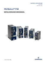
background image

Installation and User Manual 

GFK-3168A 

September 2020 

903-200003-EMR1


PACMotion

 PSD 

INSTALLATION AND USER MANUAL  


Summary of Contents for PACMotion

Page 1: ...Installation and User Manual GFK 3168A September 2020 903 200003 EMR1 PACMotion PSD INSTALLATION AND USER MANUAL ...

Page 2: ......

Page 3: ...cover all details or variations in equipment nor to provide for every possible contingency to be met during installation operation and maintenance The information is supplied for informational purposes only and Emerson makes no warranty as to the accuracy of the information included herein Changes modifications and or improvements to equipment and specifications are made periodically and these cha...

Page 4: ... Voltages 3 1 4 2 Functional Safety 3 1 4 3 Use as Directed 3 1 4 4 Prohibited Use 5 1 4 5 Warning notes placed on the product 5 Section 2 Product Life Cycle Handling 6 2 1 Transport 6 2 2 Packaging 6 2 3 Storage 6 2 3 1 Capacitor Storage 7 2 4 Installation setup and normal operation 7 2 5 Decommissioning 8 2 6 Maintenance and cleaning 8 2 7 Disassembly 8 2 8 System Repair 9 2 8 1 Exchange of the ...

Page 5: ...DPzzz07 types 240V to 480V Mains Voltage Supply 20 4 13 Cable and Wire Requirements 21 4 13 1General 21 4 14 Dynamic Braking 22 4 14 1Regen circuit 22 4 14 2Functional description 22 4 14 3Technical data for IC830DPzzz06 23 4 14 4Technical data for IC830DPzzz07 24 4 14 5Switch On and Switch Off Behavior 25 4 14 6Behavior of holding brake function 25 4 14 7Switch on behavior in standard operation 2...

Page 6: ...diagram IC830DP02406 and IC830DP00307 to 02407 62 5 9 EMI Noise Reduction 64 5 9 1 Recommendations for EMI noise reduction 64 5 9 2 Shielding with external shielding busbar 65 5 9 3 Shielding connection to the drive 67 5 10 Electrical Supply Connection 69 5 10 1Connection to various mains supply networks IC830DPzzz06 120V to 240V 69 5 10 2Connection to various mains supply networks IC830DPzzz07 24...

Page 7: ...9 2Bus Protocols X5 X6 X11 94 5 19 3EtherCAT 94 Section 6 PSD Setup 95 6 1 Important Notes 95 6 2 Setup of PSD Drives 96 6 2 1 Setup software Workbench 96 6 2 2 Use as directed 96 6 2 3 Software description 97 6 2 4 Hardware requirements 97 6 2 5 Operating systems 98 6 2 6 Installation under Windows 7 8 10 98 6 2 7 Initial Drive Test of the PSD 99 6 3 Fault and Warning Messages 103 6 3 1 Fault and...

Page 8: ...ntion to this This section helps you to recognize and avoid dangers to people and objects 1 3 2 Specialist staff required Only properly qualified personnel are permitted to perform such tasks as transport installation and setup Qualified specialist staff are persons with expertise in transport installation assembly commissioning and operation of electrotechnical equipment Transport storage unpacki...

Page 9: ...ppropriate measures to ensure that unforeseen movements cannot cause injury or damage to any person or property Additional requirements on specialist staff may also result from the risk assessment 1 3 7 Automatic Restart The drive might restart automatically after power on voltage dip or interruption of the supply voltage depending on the parameter setting Risk of death or serious injury for human...

Page 10: ...onal injury Wait at least 7 minutes after disconnecting the drive from the main supply power before touching potentially live sections of the equipment such as contacts or removing any connections Always measure the voltage in the DC bus link and wait until the voltage is below 50 V before handling components 1 4 2 Functional Safety The STO safety implementation on the PSD is qualified The assessm...

Page 11: ...ter measures for IC830DPzzz06 must be implemented by the user 1 4 3 3 For the cases of group installations and of DC powered drives PSD has not been evaluated by Emerson UL or TÜV for group installations nor are ratings defined for DC input voltage Group installations must be reviewed and evaluated by the user for branch circuit protection wire size wire voltage rating fuse protection system diele...

Page 12: ...es or standards The use of the drive in the following environments is also prohibited potentially explosive areas environments with corrosive and or electrically conductive acids alkaline solutions oils vapors dusts ships or offshore applications 1 4 5 Warning notes placed on the product IC830DP002407 IC830DP00306 P02406 P00307 P01206 WARNING HIGH VOLTAGE Wait 7 minutes after removing power before...

Page 13: ...t with highly insulating materials such as artificial fabrics and plastic films Place the drive on a conductive surface If the packaging is damaged check the unit for visible damage Inform the shipper and the manufacturer of any damage to the package or product 2 2 Packaging Model Package Dimensions mm HxWxL Total Weight IC830DP kg IC830DP00306 P00606 113 x 250 x 222 1 7 IC830DP1206 158 x 394 x 29...

Page 14: ... L2 terminals and low voltage therefore low charging current for about 30 minutes We recommend using the lowest admitted rated mains supply voltage for the servo amplifier The safer recommended procedure is the use of a variable transformer If available use a variable transformer to apply voltage in 50 Volt increments for at least 20 minutes at each step until rated voltage is reached then hold th...

Page 15: ...an the device exterior 1 Decommission the device see Section 2 5 Decommissioning 2 Casing Clean with isopropanol or similar cleaning solution DANGER HIGHLY FLAMMABLE Risk of injury by explosion and fire Observe the safety notes given on the cleaning liquid package Wait at least 30 minutes after cleaning before putting the device back into operation 3 Protective grill on fan Clean with a dry brush ...

Page 16: ...of prescribed personal safety equipment 2 8 1 Exchange of the device Only the manufacturer can repair the device Opening the device voids the warranty 1 Decommission the device see Section 2 5 Decommissioning 2 Demount the device see Section 2 7 Disassembly 3 Send the device to the manufacturer 4 Install a new device as described in the Installation Manual 5 Setup the system as described in the In...

Page 17: ...mating connectors and earthing plates Note The mating SubD and RJ45 connectors are not included in the package 3 1 Part Number Scheme Use the part number scheme for product identification only not for the order process because not all combinations of features are possible always Figure 1 Part Number Scheme Customization this code includes language version of printed material and customer specials ...

Page 18: ...ee phase supply voltage range 120 to 480 V 10 50 to 400 Hz 5 or DC Connection to higher voltage mains only via isolating transformer 103 Single phase supply possible with output power derating B6 bridge rectifier integral soft start circuit Fusing to be provided by the user DC bus link voltage range 170 to 680 VDC can be connected in parallel Output stage IGBT module with floating current measurem...

Page 19: ...ontrol Digital current controller 670 ns Adjustable digital velocity controller 62 5 µs Software option position controller 250 µs 4 1 7 Inputs Outputs 1 programmable analog input 151 1 programmable analog output 152 7 programmable digital inputs 153 2 programmable digital outputs 160 1 Enable input 153 1 STO input 54 additional digital inputs and outputs depending on variants for example PSD 4 1 ...

Page 20: ...entilation Built in fan except IC830DP00306 type Note The drive shuts down fault F234 motor has no torque in case of excessively high temperature in the control cabinet Make sure sufficient forced ventilation is supplied within the control cabinet 4 3 Mechanical Data Mechanical data Units IC830DP00306 IC830DP00606 IC830DP01206 IC830DP02406 Weight standard width kg 1 1 2 3 7 Weight extended width k...

Page 21: ...max 30 VDC 100 mA short circuit proof galvanic isolation for 250 VDC Relay outputs max 30 VDC 1A max 42 VAC 1 A time open close 10ms isolation 400 VDC contact coil 4 5 Electrical Data IC830DPzzz06 Electrical Data Units IC830D P00306 IC830D P00606 IC830D P01206 IC830D P02406 Rated supply voltage L1 L2 L3 V 3 x 120 V to 240 V 10 1 x 120 V to 240 V 10 3x240 V 10 Rated supply input frequency Hz 50 Hz ...

Page 22: ... 2 5 1 3 1 0 6 Motor inductance max mH 250 125 100 60 Thermal dissipation output stage disable W max 20 max 20 max 20 max 25 Thermal dissipation at rated current W 31 57 137 175 Noise emission low speed high speed fan dB A N A 33 39 37 43 41 56 Aux voltage supply PELV V 24 V 10 check voltage drop current B P T types without with motor brake A 0 5 1 7 0 6 1 8 0 7 1 9 1 0 2 5 current M type without ...

Page 23: ...VA 1 2 4 2 8 3 at 3x480 V kVA 1 2 2 5 5 10 Peak output power for 1 s at 3x240 V kVA 1 8 3 75 6 25 10 at 3x400 V kVA 3 6 75 10 4 16 7 at 3x480 V kVA 3 6 7 5 12 5 20 Technical data for regen circuit 42 Motor inductance min at 240 V mH 3 2 1 6 1 3 0 6 at 400 V mH 5 3 2 6 2 1 1 at 480 V mH 6 3 3 2 2 5 1 2 Motor inductance max mH 600 300 250 120 Thermal dissipation output stage disable W max 20 max 20 ...

Page 24: ...0D P00607 IC830D P01207 IC830D P02407 IC830D P04807 Switching frequency of output stage kHz 8 8 6 8 8 Voltage rise speed dU dt kV µs 7 2 Bandwidth of current controller kHz 2 5 to 4 2 to 3 2 to 3 Bandwidth of velocity controller scalable Hz 0 to 800 0 to 600 0 to 600 Bandwidth of position controller scalable Hz 1 to 250 4 8 Recommended Tightening Torques Connector Tightening Torque Nm see 23 for i...

Page 25: ...mbined with the standard fuse blocks finger safe fuse holders must be used according to IEC 60529 Examples Bussmann CH Series Modular Fuse Holders class J 3 poles CH30J3 CH14J3 Example Ferraz Ultrasafe Fuse holders class J 3 poles US3J3I 4 10 1 External power supply Drive Model Max Ampere rating Example class J Bussmann Example class J Ferraz Shawmut IC830DP00306 10A Time Delay LPJ10SP DFJ10 AJT10...

Page 26: ...10A 40A FWP xxA14F 110V to 400V gRL xxA gS 400V to 480V aR xxA IC830DP024 15A 50A 4 11 2 External DC Bus link Drive Model Ampere rating UL region example CE Region example IC830DP003 to 024 50A FWP 50A14F 110V to 400V gRL 50A gS 400V to 480V aR 50A 4 12 Connectors 4 12 1 IC830DPzzz06 and IC830DPzzz07 types Connector Type Max Cross Section 1 Current2 Voltage3 Control signals X7 X8 Terminal Connecto...

Page 27: ...Connector 8 poles 2 5 mm 14 awg 16 A 320 V Regen X3 24 A Terminal Connector 4 poles 10 mm 8 awg 30 A 1000 V Power X4 24 A Terminal Connector 4 poles 10 mm 8 awg 30 A 1000 V 4 12 3 IC830DPzzz07 types 240V to 480V Mains Voltage Supply Connector Type Max Cross Section 1 Current2 Voltage3 24V STO X1 03 to 24A Terminal Connector 3 poles 1 5 mm 16 awg 8 A 160 V Motor X2 03 to 24A Terminal Connector 6 po...

Page 28: ...or your system Interface Cross Section Cable Requirements AC connection up to IC830DP006 1 5 mm 16 awg IC830DP012 2 5 mm 14 awg IC830DP024 4 mm 12 awg 600 V minimum 75 C DC bus link regen resistor IC830DP006 1 5 mm 16 awg IC830DP012 to 24 2 5 mm 14 awg 1000 V minimum 75 C shielded for lengths 0 20 m Motor cables without choke max 25 m up to IC830DP006 1 5 mm 16 awg IC830DP012 2 5 mm 14 awg IC830DP...

Page 29: ...g 4 14 1 1 IC830DP00306 to IC830DP00606 No internal regen resistor Depending on the application requirements an external resistor can be connected 4 14 1 2 IC830DP01206 to IC830DP02406 and IC830DP00307 to IC830DP02407 With internal resistor plus the ability to connect an external resistor depending on the application requirements External regen resistors are described in the GFK 3173 PACMotion PSD...

Page 30: ...nuous regen power external resistor kW 0 48 Peak regen power external 1s kW 5 4 Absorption energy in capacitors 20 Ws 60 20 DC Bus Capacitance µF 940 IC830DP00306 External regen resistor Ohm 33 Maximum continuous regen power external resistor kW 0 77 Peak regen power external 1s kW 5 4 Absorption energy in capacitors 20 Ws 60 20 DC Bus Capacitance µF 940 IC830DP00606 External regen resistor Ohm 33...

Page 31: ...en circuit V 380 760 Overvoltage limit V 420 840 Maximum regen duty cycle 15 Type Rated data Units 240 V 400 V 480 V IC830DP00307 Internal regen resistor Ohm 33 Continuous power internal resistor W 80 Peak regen power internal resistor 0 5s kW 5 5 22 1 External regen resistor Ohm 33 Continuous regen power external resistor kW 0 77 1 5 Peak regen power external 1s kW 5 4 21 4 Absorption energy in c...

Page 32: ...utput stage 118 Events that remove the DRV ACTIVE signal trigger the holding brake to apply As with all electronic circuits the general rule applies that there is a possibility of the internal holding brake module failing Functional safety e g with hanging load vertical axes requires an additional mechanical brake which must be safely operated for example by a safety control If velocity drops belo...

Page 33: ...ics so that even when power is being supplied the drive shaft is protected against unintentional restart The chapter Safe Torque Off STO describes how to use the STO function 54 4 14 7 Switch on behavior in standard operation Figure 2 Switch On Behavior in Standard Operation The diagram below illustrates the correct functional sequence for switching the drive on Fault F602 occurs when STO 54 does ...

Page 34: ...s command internally to the drive See Workbench Online Help for configuring inputs and software commands Sometimes this enable signal is called Software Enable SW Enable DRV DISMODE DRV DISMODE controls the behavior of the drv dis command issued through Workbench or terminal or fieldbus Consult the Workbench Online Helpfor configuring 0 Disable axis immediately if velocity drops below threshold CS...

Page 35: ...tion and User Manual Section 4 GFK 3168A September 2020 Technical Description and Data 28 Figure 3 Switch Off Behavior using DRV DIS Command If velocity drops below threshold CS VTHRESH or timeout occurs brake is applied 118 ...

Page 36: ...category 2 stop according to IEC 60204 52 A digital input can be configured to bring the motor to a controlled stop and then disable the drive and apply the holding brake if present See the Workbench Online Help for information on configuring Digital Inputs If velocity drops below threshold CS VTHRESH or timeout occurs brake is applied 118 Figure 4 Switch Off Behavior Using Digital Input ...

Page 37: ...e is applied 118 Set parameter MOTOR BRAKEIMM to 1 with vertical axes to apply the motor holding brake immediately after Hardware Disable 4 14 9 1 Switch off behavior in the event of a fault The behavior of the drive always depends on the fault type and the setting of a number of different parameters DRV DISMODE VBUS UVFTHRESH CS VTHRESH and others see PACMotion Workbench Online Help for more deta...

Page 38: ... faults that cause an immediate power stage disable Figure 6 Switch Off Behavior This is a category 0 stop according to IEC 60204 52 If velocity drops below threshold CS VTHRESH or timeout occurs the motor holding brake is applied 118 Set parameter MOTOR BRAKEIMM to 1 with vertical axes to apply the motor holding brake immediately after faults ...

Page 39: ...scription and Data 32 4 14 9 3 Switch off behavior for faults that cause dynamic braking Figure 7 Switch Off Behavior for Faults that Cause Dynamic Braking This is a category 0 stop according to IEC 60204 52 If velocity drops below threshold CS VTHRESH or timeout occurs brake is applied 118 ...

Page 40: ...ription and Data 33 4 14 9 4 Switch off behavior for faults that cause a controlled stop Figure 8 Switch off behavior for faults that cause a controlled stop This is a category 1 stop according to IEC 60204 52 If velocity drops below threshold CS VTHRESH or timeout occurs brake is applied 118 ...

Page 41: ...tion The stop function is defined by IEC 60204 The Stop Category must be determined by a risk evaluation of the machine Stop function must have priority over assigned start functions The following stop categories are defined 4 15 1 Stop Category 0 Shut down by immediate switching off the energy supply to the drive machinery this is an uncontrolled shut down With the approved safety function STO 54...

Page 42: ...rgency Off The Emergency Off function is used to switch off the electrical power supply of the machine This is done to prevent users from any risk from electrical energy for example electrical impact Functional aspects for Emergency Off are defined in IEC 60364 5 53 The Emergency Off function will be triggered by the manual actions of a single person Note The result of a risk evaluation of the mac...

Page 43: ... specific IGBTs have to fail at same time The calculation shows a probability of 1 5 10 15 per hour without common cause failure Even if the STO function will be issued for a whole year this event will only happen every 100 Billion years 4 16 3 Safety instructions WARNING No Brake Power Serious injury could result when a suspended load is not properly blocked The drive cannot hold a vertical load ...

Page 44: ...ecific double fault within a very short time 54 a single movement of a maximum angle of 120 electrical can happen This effect can only happen if the drive is in the function STO Even if the STO function will be issued for a whole year this event will only happen every 100 Billion years 4 16 4 Use as directed The STO function is exclusively intended to provide a functional safe stop of the motion s...

Page 45: ...n and Data 38 4 16 6 Technical data and pinout 4 16 6 1 IC830DP003 up to IC830DP024 Reference ground is GND 24 V 10 45 mA Galvanic isolation for 250 VDC Reaction time 10 ms Figure 9 24 GND STO Pin Signal Description 1 24 24 VDC Auxiliary voltage 2 GND 24V Supply GND 3 STO STO enable Safe Torque Off ...

Page 46: ...ounding connection 4 16 8 OSSD Test Pulses Figure 10 OSSD Test Pulses Safety controllers usually check their outputs periodically during the normal operation These test procedures create pulses to the STO Enable input Note Test pulses with T1 300 µs and T2 200 ms will not have any influence to the safety relevant STO function Test pulses which are outside of this specification will switch the STO ...

Page 47: ...es 0 V 24 V F602 no yes 24 V 0 V opmode no no 24 V 24 V opmode with dot yes no When STO function is engaged during operation by separating input STO from 24 V the motor slows down without control and the drive displays the fault F602 4 16 9 2 Signal diagram sequence Single channel IC830DP003 up to IC830DP024 The diagram below shows how to use the single channel STO function for a safe drive stop a...

Page 48: ... Channel control SIL CL2 PLd Note You must test the STO function after initial start of the drive after each interference into the wiring of the drive or after exchange of one or several components of the drive Method 1 drive remain enabled Method 2 drive disabled Stop drive with setpoint 0V Keep drive enabled DANGER Do not enter hazardous area Activate the STO function for example by open ing pro...

Page 49: ...e of the pulse inhibitor is available at the STO Status outputs of the PSD and must be analyzed to achieve a sufficient diagnostic cover ratio Diagnostic with external not safe controller test with dynamic sequence test cycle with each device start minimum once per day o diagnostic cover ratio 60 Diagnostic with external safe controller test with dynamic sequence test cycle with each device start ...

Page 50: ...conventional multimeter As a rule of thumb the following assumption can be made for leakage current on our low capacitance cables at a mains voltage of 400 V depending on the clock frequency of the output stage Ileak n x 20 mA L x 1 mA m at 8 kHz clock frequency at the output stage Ileak n x 20 mA L x 2 mA m at a 16 kHz clock frequency at the output stage where Ileak leakage current n number of dr...

Page 51: ...on for stationary and mobile equipment as well as for direct contact 50 to 300 mA Protection against indirect contact personal fire protection for stationary equipment Note Recommendation In order to protect against direct contact with motor cables shorter than 5 m Emerson recommends that each drive be protected individually using a 30 mA RCD which is sensitive to all currents If you use a selecti...

Page 52: ...e Protect the drive from impermissible stresses In particular do not let any components become bent or any insulation distances altered during transport and handling Avoid contact with electronic components and contacts Note The drive will switch itself off in case of overheating Ensure that there is an adequate flow of cool filtered air into the bottom of the control cabinet or use a heat exchang...

Page 53: ...rol cabinet 34 The site must be free from conductive or corrosive materials For the mounting position in the cabinet 68 respectively 72 2 Check ventilation Check that the ventilation of the drive is unimpeded and keep within the permitted ambient temperature 34 Keep the required space clearance above and below the drive 68 respectively 72 3 Check cooling system If cooling systems are used for the ...

Page 54: ...3168A September 2020 Mechanical Installation 47 5 3 Mechanical Drawings Standard Width 5 3 1 Control cabinet layout IC830DPzzz06 standard width Figure 14 Housing Clearance for Installation Material M4 hexagon socket screws to ISO 4762 3 mm T handle Allen key ...

Page 55: ...PACMotion PSD Installation and User Manual Section 5 GFK 3168A September 2020 Mechanical Installation 48 Figure 15 Housing Clearance for Installation cont d ...

Page 56: ...Manual Section 5 GFK 3168A September 2020 Mechanical Installation 49 5 3 2 Control cabinet layout IC830DPzzz07 standard width Material M4 hexagon socket screws to ISO 4762 3 mm T handle Allen key Figure 16 Control Cabinet Layout Schematic ...

Page 57: ...PACMotion PSD Installation and User Manual Section 5 GFK 3168A September 2020 Mechanical Installation 50 ...

Page 58: ...PACMotion PSD Installation and User Manual Section 5 GFK 3168A September 2020 Mechanical Installation 51 Figure 17 Control Cabinet Layout Schematic cont d ...

Page 59: ...nd wait until it has fallen below 50 V Note Wrong mains voltage unsuitable motor or wrong wiring will damage the drive Check the combination of drive and motor Compare the rated voltage and current of the units Implement the wiring according to the connection diagram 83 and following Make sure that the maximum permissible rated voltage at the terminals L1 L2 L3 or DC DC is not exceeded by more tha...

Page 60: ... 36 or 37 Connect the mains filter with IC830DPzzz06 shielded lines between filter and drive Connect the main electrical supply Check maximum permitted voltage value 36 or 37 Check proper use of residual current circuit breakers RCD 65 Connect the PC 172 for setting up the drive 4 Check the wiring against the wiring diagrams 5 6 Wiring The installation procedure is described as an example A differ...

Page 61: ... electrically conductive connection with the largest feasible surface area between the unit indicated and the mounting plate in the control cabinet This connection is for the effective grounding of HF interference and must not be confused with the PE symbol PE protective earth safety measure as per IEC 60204 5 6 1 1 Use the following connection diagrams Overview all connections IC830DP variant 83 ...

Page 62: ... 7 Components of a servosystem 5 7 1 With IC830DPzzz06 Note Cables drawn bold are shielded Electrical ground is drawn with dash dotted lines Optional devices are connected with dashed lines to the drive The required accessories are described in the accessories manual Figure 18 Components of a Servo System v ...

Page 63: ...anical Installation 56 5 7 1 1 With IC830DPzzz07 Note Cables drawn bold are shielded Electrical ground is drawn with dash dotted lines Optional devices are connected with dashed lines to the drive The required accessories are described in the accessories manual Figure 19 IC830DPzzz07 ...

Page 64: ...PACMotion PSD Installation and User Manual Section 5 GFK 3168A September 2020 Mechanical Installation 57 5 8 Connection Overview of IC830DP Drive Connectors Figure 20 IC830DP Drive Connectors ...

Page 65: ...n PSD Installation and User Manual Section 5 GFK 3168A September 2020 Mechanical Installation 58 5 8 1 Connector assignment IC830DP00306 IC830DP00606 Figure 21 Wiring Configuration for IC830DP00306 IC830DP00606 ...

Page 66: ...PACMotion PSD Installation and User Manual Section 5 GFK 3168A September 2020 Mechanical Installation 59 5 8 2 Connection diagram IC830DP00306 IC830DP00606 Figure 22 IC830DP00306 and P00606 ...

Page 67: ...PACMotion PSD Installation and User Manual Section 5 GFK 3168A September 2020 Mechanical Installation 60 Connector assignment IC830DP01206 Figure 23 IC830DP01206 ...

Page 68: ... Installation and User Manual Section 5 GFK 3168A September 2020 Mechanical Installation 61 5 8 3 Connector Assignment for IC830DP02406 and IC830DP00307 to 02407 Figure 24 Connector Assignment for P02406 and P00307 ...

Page 69: ...Installation and User Manual Section 5 GFK 3168A September 2020 Mechanical Installation 62 5 8 4 Connection diagram IC830DP02406 and IC830DP00307 to 02407 Figure 25 Connection Diagram for P02406 and P00307 to P02407 ...

Page 70: ...PACMotion PSD Installation and User Manual Section 5 GFK 3168A September 2020 Mechanical Installation 63 ...

Page 71: ...e immunity Ground the shielding at both ends Ground all shielding with large areas low impedence with metalized connector housings or shield connection clamps wherever possible For cables entering a cabinet connect shields on all 360 of the cable Never connect a simple pigtail For more information on shielding concepts 99 With separate mains filter maintain separation of leads entering and exiting...

Page 72: ...tion 65 5 9 2 Shielding with external shielding busbar EMC filtering must be done externally by the user if necessary which requires the use of shielded cables Emerson recommends a star point shield connection for example with a shielding busbar 5 9 2 1 Shielding Concept Figure 26 Shielding Concept ...

Page 73: ... rail cross section 10 x 3 mm and drill holes in it as indicated All shield clamps required must fit between the drill holes 2 Squeeze together the coil spring and the supporting plate and push the busbar through the opening in the holder 3 Mount the busbar with the shield clamps fitted on the assembly plate Use either metal spacer bushes or screws with nuts and accessories to maintain a spacing o...

Page 74: ...Grounding plates Mount the grounding plates to the drive as shown in the photos below 5 9 3 2 IC830DP0306 to P1206 types L shape grounding plate EU only Figure 28 IC830DP02406 xzzz07 types flat grounding plate 5 9 3 3 Shield connection clamps Use shield connection clamps see accessories manual These hook into the grounding plate and ensure optimum contact between the shield and the grounding plate...

Page 75: ...hield 1 back over the cable and secure with a rubber sleeve 2 or shrink sleeve Shorten all the wires apart from the protective earth PE wire green yellow by about 20 mm so that the PE wire is now the longest wire Strip all wires and fit wire end ferrules Secure the braided shield of the cable to the shroud with a cable tie 3 and use a second tie 4 to fasten the cable Wire the connector as shown in...

Page 76: ...tion 69 5 10 Electrical Supply Connection 5 10 1 Connection to various mains supply networks IC830DPzzz06 120V to 240V Note An isolating transformer is required for 400 to 480 V networks to get a maximum voltage of 240 V 10 Figure 31 Connection to Various Mains Supply Networks xzzz06 120 V to 240 V ...

Page 77: ...Mechanical Installation 70 5 10 2 Connection to various mains supply networks IC830DPzzz07 240V to 480V Note An isolating transformer is required for 120V networks to get a minimum voltage of 240 V 10 Figure 32 Connection to various mains supply networks IC830DPzzz07 240V to 480V ...

Page 78: ...am describes external 24 VDC power supply electrically isolated for example via an isolating transformer The required current rating depends on the use of motor brake card 36 or 37 Figure 33 24V Auxiliary Supply 5 10 3 1 IC830DP003 to 024 connector X1 Pin Signal Description 1 24 24 VDC Auxiliary voltage 2 GND 24V Supply GND 3 STO STO enable Safe Torque Off ...

Page 79: ... types of supply networks is possible with an additional isolating transformer 102 Periodic overvoltages between phases L1 L2 L3 and the housing of the drive must not exceed 1000 V peak In accordance with IEC 61800 voltage spikes 50 µs between phases must not exceed 1000 V Voltage spikes 50 µs between a phase and the housing must not exceed 2000 V IC830DP00306 to IC830DP00606 X3 Pin Signal Descrip...

Page 80: ... September 2020 Mechanical Installation 73 5 10 4 1 Three phase connection Fuses all PSD types 3 phase supply network supply networks 102 Filtering for IC830DPzzz06 to be provided by the user Fusing to be provided by the user 39 Figure 34 Three Phase Connection km ...

Page 81: ...30DP00306 to IC830DP01206 only Single phase supply network 120 V 10 to 240 V 10 with neutral line or Two phase supply network 120 V 10 to 240 V 10 without neutral line Supply networks 102 Leave L3 open circuit Filtering to be provided by the user Fusing such as fusible cut outs to be provided by the user 39 Figure 35 Single Dual Phase Connection ...

Page 82: ...elded single cores with a max length of 200 mm use 6 mm shielded cables for longer lengths In this case no fuse for line protection is required Use 16 mm unshielded single cores with a max length of 30 mm use 16 mm shielded cables for longer lengths Note Drives can be destroyed if DC bus link voltages are different Only drives with mains supply from the same mains identical mains supply voltage ma...

Page 83: ...become damaged or destroyed if for example a device fails due to an internal short circuit If multiple drives are connected in parallel then it is usual to insert DC Bus fuses 39 between groups of drives with a group consisting of two or three devices depending on the current in order to limit any possible resulting dam age Fuses cannot avoid damage by current peaks completely Figure 37 DC Bus Top...

Page 84: ...39 are tripped and the rest of the network continues uninterrupted The solid busbars can conduct significantly larger currents because the compensating current does not flow through the connector as above For this reason almost as many drives as desired can be connected in parallel in this form Figure 38 DC Bus Topology with Busbar 5 11 3 External regen resistor X3 For technical data on the brake ...

Page 85: ... to 400 V gRL gS 400 V to 480 V aR IC830DP024 15 A 50 A IC830DP00306 to IC830DP00606 X3 Pin Signal Description 1 RB External Regen Resistor negative 3 RB External Regen Resistor positive IC830DP01206 X3 Pin Signal Description 1 Rbint Internal Regen Resistor positive 2 RB External Regen Resistor negative 4 RB External Regen Resistor positive IC830DP02406 IC830DP00307 to IC830DP02407 X3 Pin Signal D...

Page 86: ...sor is connected and supervised With Emerson motors the valid data are automatically set by the internal motor database Refer to parameter MOTOR RTYPE for supported thermal sensors Note the dynamic voltage rise can lead to a reduction in the motor operating life and on unsuitable motors to flashovers in the motor winding Only install motors with insulation class F acc to IEC60085 or above Only ins...

Page 87: ...12 1 1 Cable length 25 m Cable length 25 m Figure 41 Cable Length 25 M Signal Description 1 BR Motor holding brake 118 2 BR Motor holding brake 118 3 PE Protective earth motor housing 4 U Motor phase U 5 V Motor phase V 6 W Motor phase W 5 12 2 IC830DP003 to 024 power connector X2 Figure 42 IC830DP003 to 024 ...

Page 88: ...his function does not ensure functional safety Functional safety e g with hanging load vertical axes requires an additional mechanical brake which must be safely operated for example by a safety control The Hardware Enable connector X8 pin 4 does not initiate a controlled stop but switches off the power stage immediately Set parameter MOTOR BRAKEIMM to 1 with vertical axes to apply the brake immed...

Page 89: ...er 2020 Mechanical Installation 82 5 13 1 IC830DP003 to 024 brake connector X2 Brake voltage supply via 24 V 10 auxiliary voltage supply of the drive on X1 Maximum cur rent depends on the drive type see Technical Data 36 or 37 Figure 43 ALD x003 to 024 brake connector X2 ...

Page 90: ...ed and braking force All values can be adjusted with parameters values in the diagram are default values The speed setpoint of the drive is internally driven down an adjustable ramp CS DEC to 0 V With default values the output for the brake is switched on when the speed has reached 120 rpm CS VTHRESH for at least 6 ms CS TO The rise tbrH and fall tbrL times of the holding brake that is built into ...

Page 91: ...ck device Feedback functions are assigned with parameters in PACMotion Workbench the setup software Scaling and other settings are also performed in PACMotion Workbench For a detailed description of the parameters please refer to the PACMotion Workbench Online Help The table below provides an overview of the supported feedback types their corresponding parameters and a reference to the relevant co...

Page 92: ...edback connector X10 Figure 45 Feedback Connector x10 Pin SFD3 Hiperface BiSS B analog 1 2 CLK 3 CLK 4 SEN SEN 5 SEN SEN 6 COM DAT DAT 7 COM DAT DAT 8 Th Th 9 Th Th 10 8 to 9 V 8 to 9 V 5 V 11 0 V 0 V 0 V 12 SIN A 13 SIN A 14 COS B 15 COS B CLK CLOCK DAT DATA SEN SENSE Th thermal control for PSD with NB rev 8 only ...

Page 93: ...iagram below shows the connection of the two wire Emerson SFD3 feedback system SFD3 can be used with the special Emerson cable Maximum cable length is up to 25 m Type FBTYPE Up Remarks SFD3 45 8 to 9 V from FW 1 11 with Emerson Cables only Figure 46 SFD3 For pin assignment on the motor side refer to the motor documentation ...

Page 94: ... is pressed The two digits LED display indicates the PSD mes sages Fault messages are coded with F warnings are coded with n The one digit LED indicates the PSD messages of the PSD Error messages are coded with E warnings alarms are coded with A Status of applic ation programs are indicated as well With push but tons B2 and B3 a menu with several functions can be started 169 See PACMotion Workbenc...

Page 95: ...sed to select IP address or predefined functions for executing PSD S1 S2 5 16 1 Rotary Switches S1 and S2 with PSD Drives S 1 S 2 Function Set while Remarks 0 0 DHCP IP 24 V is OFF The drive acquires its IP address from an external DHCP server details see 174 x y Static IP 24 V is OFF The IP address is 192 168 0 nn valid values are 01 to 99 details see 174 ...

Page 96: ...e used to start predefined functions Figure 47 B1 B2 B3 5 17 1 Push Button B1 with PSD Drives Function Push button Remarks Display IP address B1 Press short to display the IP address in the two digit display Switches Drive Type of IC830DP CC model B1 Set rotary switches S1 to 8 and S2 to 9 Press B1 for 3 sec to switch over from CAN to EtherCAT or reverse ...

Page 97: ...d off Use standard Cat 5 Ethernet cables for connection in some cases crossover cables will also work Confirm that the link LED on the PSD the green LED on the RJ45 connector and on your PC or network Hub Switch are both illuminated If both lights are illuminated then you have a good electrical connection Color Name Indication Green Link On receive signal valid Yellow Activity Blink Transmit or Re...

Page 98: ... 48 Network Configuration Example 5 18 4 Setting the IP Address IC830DP Figure 49 Setting IP Address The IP address can be flashed across the LED display if the B1 button is pressed You can use the rotary switches to set the IP address of the PSD For some fieldbuses the rotary switches also set the node address of the drive for that specific network ...

Page 99: ...table above 5 18 4 2 Dynamic IP addressing DHCP and Auto IP With S1 and S2 both set to 0 the drive is in DHCP mode The drive will acquire its IP address from an external DHCP server if present in the network If a DHCP server is not present the drive will assume an Automatic Private IP Address of the form 169 254 x x If your PC is directly connected to the drive and set to obtain an IP address auto...

Page 100: ...ay will flash 0 0 0 0 and then attempt to discover an address by DHCP Without removing logic power from the drive use PACMotion Workbench to connect to the drive reconfigure the IP address settings as desired and store the values to non volatile memory 5 19 EtherCat Interface X5 X6 EtherCat The motion bus interface has RJ 45 connectors and can be used for communicating with various fieldbus device...

Page 101: ...cols X5 X6 X11 Protocol Type Connectivity Option Connect or EtherCAT Motion bus EC or CC X5 X6 5 19 3 EtherCAT PSD drives connection variants EC can be connected as slaves to the EtherCAT network CoE via RJ 45 connectors X5 in port and X6 out port The communication status is indicated by the built in connector LEDs Drive variant Connector LED Name LED function ON LED function OFF PSD X5 LED1 Link ...

Page 102: ...ne The drive might restart automatically after power on voltage dip or interruption of the supply voltage depending on the parameter setting If parameter DRV ENDEFAULT is set to 1 then place a warning sign WARNING Possible Automatic Restart or similar to the machine Ensure that power on is not possible while personnel are in a dangerous zone of the machine CAUTION HIGH TEMPERATURE Risk of minor bu...

Page 103: ... the operating parameters for the PSD series of drives The attached drive can be set up with the help of this software and during this procedure the drive can be controlled directly by the service functions Only professional personnel who have the relevant expertise 14 are permitted to carry out online parameter setting for a drive that is running Sets of data that have been stored on data media a...

Page 104: ...e PC oscilloscope functions You can save sets of data on data media archiving and load them into other drives or use them for backup You can also print out the data sets Most standard feedbacks SFD3 BiSS and HIPERFACE DSL are plug and play compatible Motor nameplate data is stored in the feedback device and read by the drive automatically at startup Non plug and play Emerson motors are stored in P...

Page 105: ...e user s machine a dialog window will appear with a link to Emerson s Customer Center From there the user can locate and download a licensed copy of PACMotion Workbench From DVD Workbench installs automatically from the DVD included with the drive Workbench is also available on the Emerson support site Links are provided at the end of this manual Once the installation is complete click the Workben...

Page 106: ...Initial Drive Test of the PSD 6 2 7 1 Unpacking mounting and wiring the PSD Unpack the drive and accessories Observe the safety instructions in the documentation Mount the drive Wire the drive or apply the minimum wiring for drive testing as described below Make sure you have on hand the following information about the drive components o rated mains supply voltage o motor type motor data if the mo...

Page 107: ...atic IP addressing not 00 is recommended Figure 52 Minimum Wiring for Drive Test without Load 6 2 7 3 Set IP address Set the drive IP address as described in 174 6 2 7 4 Confirm connections You can turn on logic power to the drive through the X1 connector bus voltage is not needed for communications After power is supplied the drive displays a sequence of LED flashes 1 2 3 4 I P 5 Drive IP address...

Page 108: ...3 LED While the PC is connecting your status bar will show the following acquiring icon Figure 54 Status Bar Acquiring Connection Wait for this icon to change to the limited functionality icon this process can take up to one minute Figure 55 Status Bar Connection Complete Although Windows displays this limited functionality icon for the drive connection the PC can communicate fully with the drive ...

Page 109: ...ew screen appears Your drive appears in the navigation area on the left of the screen Right click on your drive name and select Setup Wizard from the drop down menu The Setup Wizard guides you through the initial drive configuration which includes a simple test motion After completing the Setup Wizard your drive should be enabled If the drive is not enabled check the following 3 The hardware enabl...

Page 110: ...AULTS through the controller or HMI for the entire list of faults Note Eliminate errors and faults in compliance with work safety rules Troubleshooting only by qualified and trained staff Note More information about fault messages remedy and clearing faults can be found in the PACMotion Workbench Online Help Code Message Warning 24V power X1 overload or 5V X9 shorted F0 Reserved F101 n101 Firmware...

Page 111: ...zed n171 Motion task activation is currently pending n174 Homing maximum distance exceeded n179 Teaching of cogging compensation stopped before finishing n180 Cogging compensation not active Axis needs to be homed first F201 Internal RAM failed F202 External RAM failed F203 Code integrity failed F204 to F232 EEPROM failure detected F234 to F237 n234 to n237 Temperature sensor high F240 to F243 n24...

Page 112: ...mutation not possible F470 Feedback fault on feedback 3 F471 Operation in Position Mode with Halls Only feedback not allowed F473 Wake Shake Insufficient movement F475 Wake Shake Excess movement F476 Wake Shake Fine coarse delta too large F478 n478 WWake Shake Over speed F479 n479 Wake Shake Loop angle delta too large F480 Wake Shake Fieldbus command velocity too high F481 Wake Shake Fieldbus comm...

Page 113: ...ot prevent over voltage F570 n570 Mains phase loss n580 Using derivate of position with sensorless feedback type in position mode n581 Zero velocity with induction sensorless feedback type in position mode n582 Velocity has been limited commutation frequency max 599 Hz to meet ECCN 3A225 AL 3A225 limits F587 Loss of all AC input phases n601 Modbus data rate is too high F602 Safe torque off n603 OP...

Page 114: ...t software enable Check setpoint cable Correct motor phase sequence Check brake control Check mechanics Set motor pole no Set up feedback correctly Motor oscillates Gain is too high speed controller Feedback cable shielding broken AGND not wired up Reduce VL KP speed controller replace feedback cable Join AGND to CNC GND Drive reports following error Lrms or Ipeak set too low Current or velocity l...

Page 115: ......

Page 116: ...turns customercare cn mas emerson com Technical Support support mas apac emerson com Any escalation request should be sent to mas sfdcescalation emerson com Note If the product is purchased through an Authorized Channel Partner please contact the seller directly for any support Emerson reserves the right to modify or improve the designs or specifications of the products mentioned in this manual at...

Reviews: