background image


  Single Motor (Hub) and Remote


IMPORTANT:

 Prior to motor network setup, install batteries into the SUITE Remote and wait for the LEDs to go out (“asleep”). 


  Create the Hub Motor


— Power up one factory default motor which automatically establishes it as the Hub.
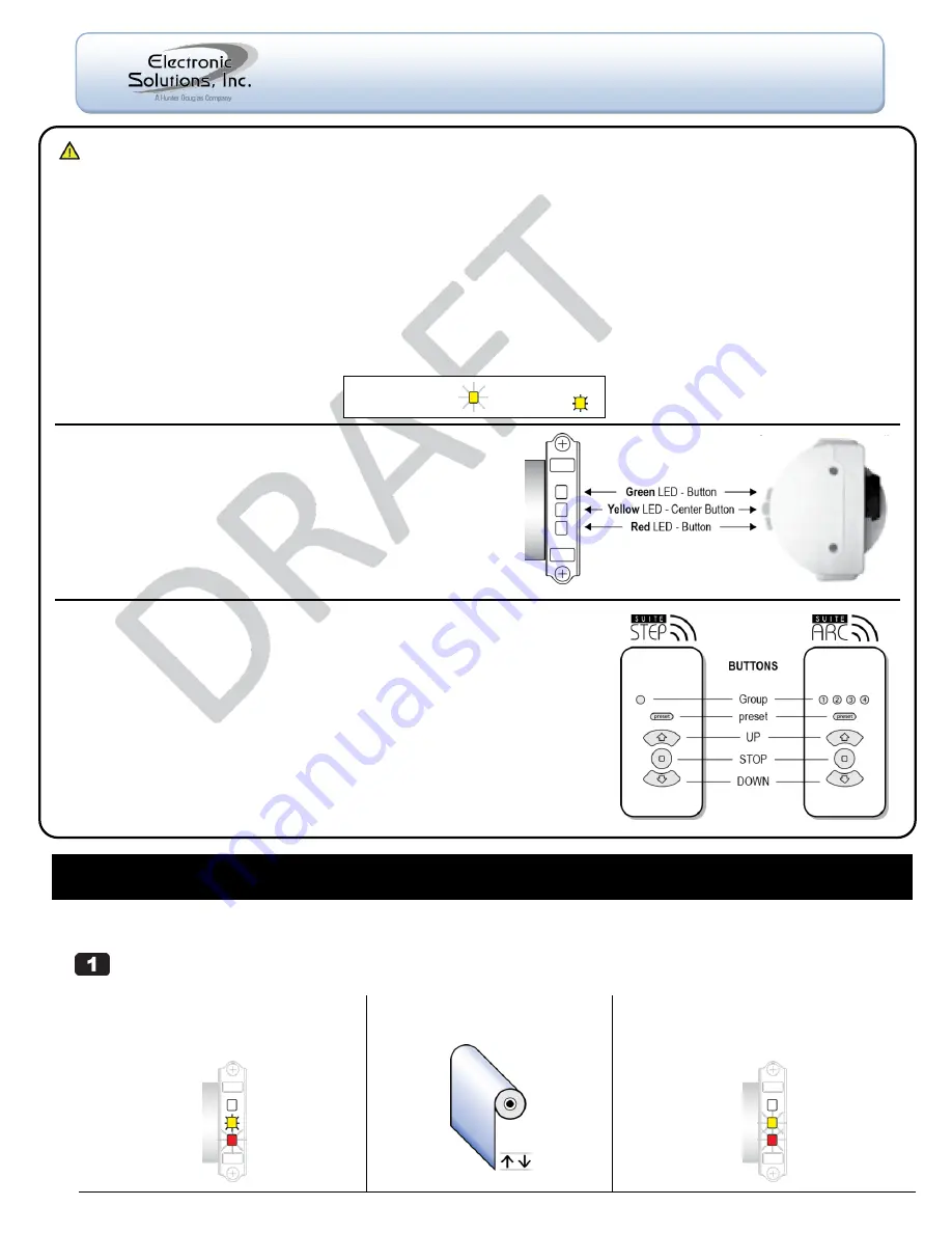
1


(a)  Connect AC power to the motor. 


On motor, Yellow LED is solid and Red LED is 
flashing (indicates end limits are not set).

2


(b) Wait until motor jogs twice. 


Could take up to 3 minutes. 


(c)  Motor is now the Hub motor. 


Yellow LED begins flashing for 60 seconds 
(indicates Network Invite Mode).

3


  Important Installation Information


When shipped, the remote is in Setup Mode to facilitate creation of a motor network. 


When network creation is finished and ready for the end user, you must exit Setup Mode on the remote. 


For best RF performance, the antenna on the motor should maintain as much separation from a conductive surface as possible. 

Glossary 

Hub Motor

 - Special designation for the first motor powered up. All commands to additional motors are routed through the Hub motor. 

Jog Once

 - Motor moves a short distance in one direction. 

Jog Twice

 - Motor moves a short distance in two directions. 

Remote

 - The RF transceiver used to set up and operate motors.  

Asleep

 - The defau

lt state of a remote is ―asleep‖ — no LEDs are lit. ―Wake Up‖ remote: press and release the UP or DOWN button. 

Group 

- A collection of up to four motors controlled by Group 1, 2, 3, or 4 on an Arc transceiver or Group 1 on a Step transceiver. 

LED

 - Light-emitting diode. Both the remote and the motor head have LEDs in three colors. 

Blink

 - A single on/off of an LED. 

Flash

 - LED turns on and off continuously. 


M40/50RF Motor 

The M40/50RF motor is equipped with radio frequency technology 
and has three buttons with internal LEDs that provide visual 
feedback during setup and operation. 

Green

 LED 

– Button operates the motor in one direction. 

Yellow

 LED 

– Center Button is used for motor administration. 

Red

 LED 

– Button operates the motor in the other direction. 


SUITE Remote 

The SUITE Remote is equipped with radio frequency technology for wireless control 
of all ESI RF-enabled motors. 


The SUITE Step remote controls one group of up to four motors. 


The SUITE Arc remote controls four groups of up to four motors each, for a total of sixteen motors. 


Wake Up the Remote


The 

remote must be ―awake‖ to send or receive commands.


To wake up a remote that is 

―asleep‖ (no LEDs are lit): 


Press and release the UP or DOWN button. 


NOTE

:  When no buttons are pressed, the remote goes to sleep after 10 seconds 

while in User Mode, or after 60 seconds while in Setup Mode. 


Blink or Flash = 


Solid = 


M40/50RF System 


Quick Setup Guide


© 2011 Electronic Solutions, Inc. 

1355 Horizon Avenue, Lafayette, CO 80026 U.S.A. 

Tel: (303) 469-9322 

www.elec-solutions.com


Summary of Contents for M40RF

Page 1: ...e lit Wake Up remote press and release the UP or DOWN button Group A collection of up to four motors controlled by Group 1 2 3 or 4 on an Arc transceiver or Group 1 on a Step transceiver LED Light emitting diode Both the remote and the motor head have LEDs in three colors Blink A single on off of an LED Flash LED turns on and off continuously M40 50RF Motor The M40 50RF motor is equipped with radi...

Page 2: ...twice e Remote is in Setup Mode Red LED under preset is solid and Yellow LED under Group 1 is solid The UP and DOWN buttons are flashing indicates no end limits are set Toggle Motor Direction Check the motor travel direction using the remote a Verify travel direction Press the UP or DOWN button If the shade moves as expected skip to Step 4 b Toggle the motor direction Simultaneously press and hold...

Page 3: ...outside of a current end limit you must clear that end limit first Clear Upper Limit Simultaneously press and hold STOP and UP until motor jogs twice then jogs once approximately 5 seconds then release The UP button flashes to show its limit is cleared Clear Lower Limit repeat the above two instructions using the DOWN button instead of UP b Set the new Upper or Lower end limit UPPER see Step 4 a b...

Page 4: ...r jogs once Next motor Hub motor f On the remote Red LED under preset is solid Yellow LED under Group 2 is solid if it is the 2nd motor 3 if it is the 3rd motor and so on The UP and DOWN buttons are flashing indicates no end limits are set Toggle Motor Direction Set Limits Adjust Limits Clear Limits a Make sure the correct Group Number is selected on the remote for the 2nd motor for the 3rd motor ...

Page 5: ... motor it will jog twice The motor has now moved into the first available position within the new group NOTE In Setup Mode only one motor can be selected at a time In User Mode one or more groups of motors can be selected Finish the Installation a On the remote you must exit Setup Mode and put the remote into User Mode after the installation is complete Hold 1 and briefly press and release STOP Re...

Page 6: ...ice information factory default Press and hold preset and STOP after 2 seconds UP and DOWN turn on solid To REBOOT Release preset and STOP when the UP and DOWN LEDs are on solid The remote enters Setup Mode immediately after rebooting To RESET Release preset and STOP after the UP and DOWN LEDs go out about 5 seconds The remote enters Network Search Mode immediately after resetting A reboot functio...

Page 7: ...s of blinks to show the firmware version not described in this document 3 Network Invite Mode is a 60 second time frame when a motor or remote is looking for other devices to join the network 4 Network Search Mode is a 30 second time frame when a remote looks for other devices to join when no network is present Technical Information SUITE Remote Batteries 3 AAAA Operating Frequency RF 2 4 GHz Radi...

Reviews: