Electro-Voice REV, Operating Instructions Manual
The Electro-Voice REV, a cutting-edge audio device, offers an exceptional audio experience. Seamlessly navigate its innovative features with the Operating Instructions Manual, available for free download on our website. Unlock the full potential of your REV and enrich your listening moments with our comprehensive user manual.
Share
Download


Reviews:
No comments
Related manuals for REV
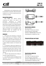
DM-50
Brand: GATT AUDIO Pages: 2

RM Series
Brand: Yamaha Pages: 42

ES925H6/DS3
Brand: Audio Technica Pages: 5

4R70W
Brand: US Shift Pages: 36

shift selector
Brand: Allison Transmission Pages: 24

Dummy Head KU 100
Brand: Neumann.Berlin Pages: 20

Mh-700
Brand: JTS Pages: 28

A1
Brand: REMOVU Pages: 40

SpeechWare TableMike
Brand: Speech Recognition Solutions Pages: 13

MicroComm DXI DSM-140
Brand: Harding Instruments Pages: 3

surflink
Brand: Paradigm Pages: 28

CMI-8000-AN
Brand: ConnectIT Pages: 24

DYN P48 Series
Brand: Schertler Pages: 16

GN 15 ESP
Brand: Audio Vias Pages: 3

EC Series
Brand: Shure Pages: 8

Drum Bundle PGADRUMKIT4
Brand: Shure Pages: 9

KSM44
Brand: Shure Pages: 12

WESII-AA
Brand: KBC Pages: 48


