


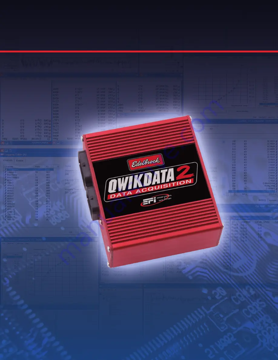
Edelbrock QwikData 2
Quick Start Guide
This QwikData 2 QwikStart guide is a condensed installation manual, outlining the basic setup functions to get your
data acquisition system up and running.
For more detailed information and to better familiarize yourself with the power of QwikData 2 Data Logger System,
please review the QwikData 2 Installation Manual and the Help Menu included in your software.
#63-91270QS
Summary of Contents for QwikData 2
Page 27: ...26 Getting Started Edelbrock QwikData 2 Suggested Harness Routing...
Page 28: ...27 Getting Started Edelbrock QwikData 2 91290 Basic Analog Harness Details...
Page 29: ...28 Getting Started Edelbrock QwikData 2 91290 Basic Harness Schematic...
Page 31: ...30 Getting Started Edelbrock QwikData 2 91294 Advanced Thermocouple Harness Details...
Page 32: ...31 Getting Started Edelbrock QwikData 2 91294 Advanced Thermocouple Harness Schematic...
Page 34: ...33 Getting Started Edelbrock QwikData 2 91291 Advanced Analog Harness Details...
Page 35: ...34 Getting Started Edelbrock QwikData 2 91291 Advanced Analog Harness Schematic...
Page 39: ...38 Getting Started Edelbrock QwikData 2 User Notes...


