Earth Stove Natural FIRE MP250, Installation And Operation Manual
The Earth Stove Natural FIRE MP250 is a powerful and efficient wood stove that provides warmth and ambiance to any space. Make sure to read the Installation And Operation Manual before use. You can download the manual for free from manualshive.com. Enjoy the benefits of this reliable heating source.
Share
Download


Reviews:
No comments
Related manuals for Natural FIRE MP250
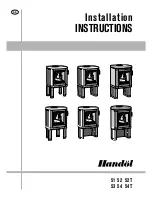
51
Brand: Handöl Pages: 16

90-60 PF2
Brand: barbas Pages: 96

SIERRA
Brand: Panadero Pages: 16
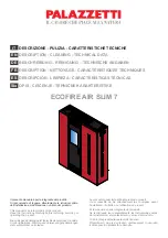
ECOFIRE AIR SLIM 7
Brand: Palazzetti Pages: 24

DOMUS
Brand: Horus Pages: 109

MIRAGE 30 SERIES A
Brand: Pacific energy Pages: 36

Willow
Brand: Valor Pages: 22

Millennium 31M-ACC-MBK
Brand: Quadra-Fire Pages: 56

SQUARE 68 - SCHEMATICS
Brand: WANDERS Pages: 1

NC-40
Brand: Nature's Comfort Pages: 31

79654
Brand: Nor-Varm Pages: 25

Heatranger 480GB
Brand: Rayburn Pages: 37

Talisman
Brand: Logaire Pages: 12

GEO
Brand: RAIS Pages: 40

Atlantic 600
Brand: Lacunza Pages: 24

Little Thurlow
Brand: Town & Country Fires Pages: 12

ECOFIRE AUDREY
Brand: Palazzetti Pages: 16

LINDA US 12
Brand: Palazzetti Pages: 144


