background image


P

P

P

P

P

P

P

P

S

S

S

S

S

S

S

S

T

T

T

T

T

T

T

T

-

-

-

-

-

-

-

-

8

8

8

8

8

8

8

8

0

0

0

0

0

0

0

0

0

0

0

0

0

0

0

0

0

0

0

0

0

0

0

0


U

U

U

U

U

U

U

U

ssss

ssss

e

ee

e

e

ee

e

rrrr

rrrr

''''

''''

ssss

ssss


M

M

M

M

M

M

M

M

a

a

a

a

a

a

a

a

n

n

n

n

n

n

n

n

u

u

u

u

u

u

u

u

a

a

a

a

a

a

a

a

llll

llll


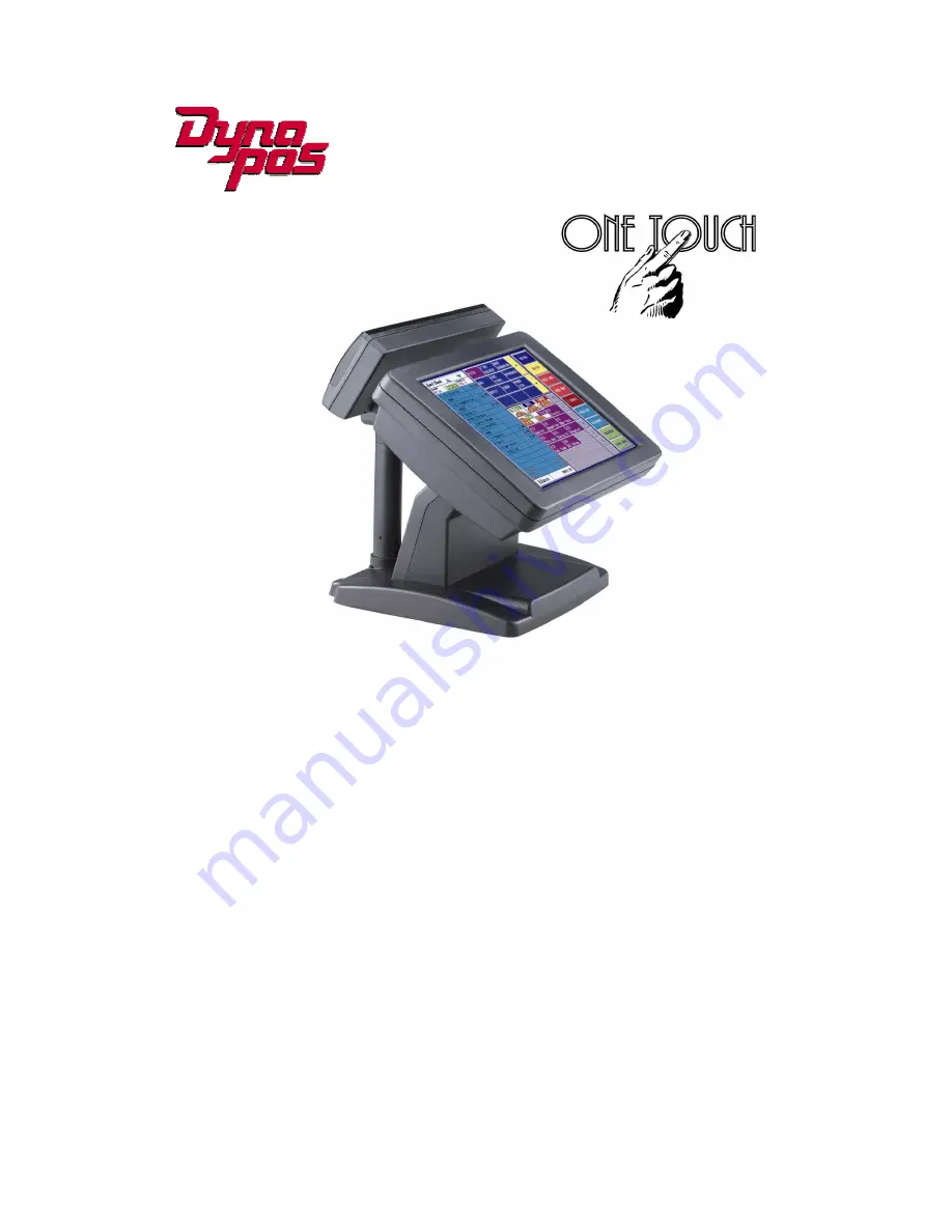
PEB-4720 Main Board, 12.1 & 15 inch LCD’s

Summary of Contents for PST-8000

Page 1: ...8 80 0 0 0 0 0 0 00 0 0 0 0 0 0 00 0 0 0 0 0 0 0 U U U U U U U Us s s s s s s se e e e e e e er r r r r r r r s s s s s s s s M M M M M M M Ma a a a a a a an n n n n n n nu u u u u u u ua a a a a a a...

Page 2: ...rienced radio TV technician for help Shielded interconnect cables and shielded AC power cables must be employed with this equipment to insure compliance with the pertinent RF emission limits governing...

Page 3: ...ust be rated for the product and for the voltage and current marked on the product s electrical ratings label The voltage and current rating of the cord should be greater than the voltage and current...

Page 4: ...ains information protected by copyright No part of this manual may be photocopied or reproduced in any form without prior written consent from the manufacturer 2001 All rights reserved The software de...

Page 5: ...rawer Installation 18 Cash Drawer Activation 19 Optional Second LCD Panel Display 20 OSD Settings for Second LCD Panel 21 CMOS Setup 22 C Ch ha ap pt te er r 3 3 2 23 3 Software Setup 23 Please follow...

Page 6: ...5 I O board Configuration 57 9000PB0700 I O Board Pin Definition 57 9000PB0710 I O Board Pin Definition 61 9000PB0230 I O Board Pin Definition 65 C Ch ha ap pt te er r 5 5 6 67 7 Troubleshooting 67 Po...

Page 7: ...The primary LCD panel can be tilted at multiple angles Model H700 s functionality extends far beyond the standard setup Model H700 can be adapted for a variety of uses with the addition of any of the...

Page 8: ...to Model H700 and this manual Chapter 2 Provides all necessary information for all hardware setup Chapter 3 Provides the necessary information for installing the Intel Chip set driver Video drivers an...

Page 9: ...4720 Main Board 3 A Visual Tour of Model H700 Before you start take a few moments to become familiar with Model H700...

Page 10: ...ard with Model H700 Main system with LCD panel Base ATX power supply Model H700 user s guide 4720 motherboard user s guide ELO touch screen driver CD Utility and Motherboard chipset driver CD AC power...

Page 11: ...20 Main Board 5 The following items are optional Magnetic card reader MCR and bracket External CD ROM drive with cable External USB floppy disk drive with cable VFD customer display Optional accessori...

Page 12: ...4720 Main Board 6 Dimensions 12 1 Model H700 Dimensions Model H700 and MCR Dimensions Model H700 and VFD customer display...

Page 13: ...4720 Main Board 7 Dimensions 15 Model H700 Dimensions Model H700 and MCR Dimensions Model H700 and VFD customer display...

Page 14: ...port for an external keyboard Mouse PS 2 Mouse Connector PS2 ports can be used for a mouse COM1 COM2 DSUB Connector The serial ports COM1 COM2 can be used to connect serial devices such as a mouse or...

Page 15: ...panel is located on the left side of the back of the main unit It comes with a cover that needs to be removed to install a CD ROM Driver I O Port Connector Type Description CD ROM 36 PIN SCSI II Conn...

Page 16: ...700 and 9000PB0710 located on the back of the neck The rear neck plate must therefore be removed before alterations can be made to the hardware As an example to set up for DC 5V or DC 12V at Pin9 of C...

Page 17: ...main unit 2 Remove the Base HDD Plate from the base 4 screws 3 Secure the hard disk drive on the plate 4 screws 4 Plug the IDE and power cable to the HDD The red stripe on the ribbon cable should be a...

Page 18: ...act Flash Installing Compact Flash 1 Turn off power and remove power cable from Model H700 2 As the compact Flash socket is located on the soldering side of M B remove the 4 screws and disassemble the...

Page 19: ...of Model H700 Installing an MCR 1 Turn off system power 2 Unplug the loopback from the MCR socket The MCR socket is found on the right side on the back of the main Unit 3 Attach the MCR Assembly to th...

Page 20: ...14 5 Turn on system power Note If the MCR does not work normally please refer to troubleshooting Attention The loopback or the MCR cable must be inserted in the socket for an external keyboard to func...

Page 21: ...older of your choice It will also create 3 subfolders named Disk1 Disk2 and Disk3 Change to the folder Disk1 and run the Setup exe program and follow the simple onscreen instructions When the installa...

Page 22: ...jumpers on the secondary I O board 9000PB0710 are set correctly It s important to note that the supply voltage for the VFD customer display is set to 12V If an LCD customer display is chosen please c...

Page 23: ...cable in the VFD COM4 port on the I O panel which located under the base V F D C O M 4 7 Turn on VFD power switch then turn on system power Note If the VFD does not display correctly after an applicat...

Page 24: ...roubleshooting Cash Drawer Installation 1 Before connecting the cash drawer to Model H700 please make sure the driver voltage and cable pin assignment of the cash drawer matches the definition of the...

Page 25: ...wer number 2 O 2F 02 This will power the cash drawer number 2 solenoid ON Wait 200 milliseconds O 2F 00 This removes the power from the cash drawer solenoid There is only one input for the Cash Drawer...

Page 26: ...d Panel Display Pole and Holder to the base and secure firmly with the 3 screws Now connect the Second Panel Display cables to the Power and VGA sockets on the underside of the Model H700 unit If you...

Page 27: ...buttons are as follows Menu Press to open the OSD window Back one menu level up Press to exit the OSD window while in OSD mode DownArrow Press to scroll item selection bar down To decrease the parame...

Page 28: ...PEB 4720 Main Board 22 CMOS Setup Model H700 systems have adopted the motherboards 4720 using AWARD BIOS Please refer to the 4720 M B User s Manual for a detailed description of the BIOS CMOS setup...

Page 29: ...quence exactly Driver installation sequence Chipset Driver VGA Driver LAN Driver Audio Driver USB Driver Touch Tools FIX COM PORT Tools The reason to follow our sequence is that IRQ settings will be c...

Page 30: ...720 Main Board 24 5 Read the License Agreement and click Yes 6 Click Next and the drivers for the Intel Chip set will install 7 When the Setup COMPLETE message appears click Finish to restart your com...

Page 31: ...s capable of driving a single or dual panel display Only one driver needs to be installed 852GME driver installation Windows 98 ME 1 Locate the VGA folder on the utilities CD 2 Open D PEB 4720 GRAPHIC...

Page 32: ...PEB 4720 Main Board 26 6 Read the License Agreement and click Yes 7 Click Finish to complete the installation procedure and restart the system...

Page 33: ...PEB 4720 Main Board 27 8 When entering Windows Windows will find new hardware Insert Disk Open D PEB 4720 GRAPHIC INTEL WIN9X WIN9X ikch8xx cat folder Click OK...

Page 34: ...PEB 4720 Main Board 28 852GME driver installation Windows 2000 XP 1 Open D PEB 4720 GRAPHIC INTEL WIN2KXP folder 2 Run setup exe 3 Select Next to continue 4 Select Next to continue...

Page 35: ...PEB 4720 Main Board 29 5 Read the License Agreement and click Yes 6 Click Finish to complete the installation procedure and restart the system...

Page 36: ...Enable second LCD panel setting Windows 2000 Windows XP After you have installed the VGA driver you must adjust the settings 1 Right click your mouse anywhere on the desktop then click properties 2 C...

Page 37: ...PEB 4720 Main Board 31 3 Click Advanced 4 Click Intel R Extreme Graphics...

Page 38: ...PEB 4720 Main Board 32 5 Click Graphics Properties 6 Click Extended Desktop and select Notebook for primary device monitor for secondary device...

Page 39: ...ng from the dropdown menu For the second LCD panel make sure that Extend my Windows desktop onto this monitor is selected 9 Click Apply then click OK to finish the settings Note During boot sequence N...

Page 40: ...ard 34 LAN Driver Installation Realtek LAN Driver Installation Windows 98 1 Open Device Manger in the System Properties Select PCI Ethernet Controller Click Properties 2 Select the General tab Click R...

Page 41: ...PEB 4720 Main Board 35 3 Click Next 4 Select Search for a better driver then the one your device is using now Recommended Click Next 5 Select The updated driver Recommended Click Next...

Page 42: ...rd 36 6 Click Next 7 Click Finish 8 Click Yes to restart your computer Realtek LAN Driver Installation Windows 2000 and Windows XP After Windows 2000 is installed the Realtek LAN driver will be automa...

Page 43: ...Installation Audio Driver Installation for all Windows Operating Systems 1 Open D PEB 4720 AUDIO WDM 2 double click Setup exe 3 Select Next to continue Note For Windows 2K If you receive this warning...

Page 44: ...PEB 4720 Main Board 38 Note For XP If you receive this warning message please click Continue Anyway 4 Click Finish and restart the system...

Page 45: ...PEB 4720 Main Board 39 USB Driver Installation USB 2 0 Installation for Windows 98 ME 1 Open D PEB 4720 USB20 WIN9X 2 double click Setup exe 3 Read the License Agreement and click Yes 4 Click Close...

Page 46: ...0 support For Windows XP SP1 or SP2 must be installed for USB 2 0 support Note with lower version service packs only USB 1 1 is supported This will be indicated in the device manager as an exclamatio...

Page 47: ...llation for Windows 98 1 Insert the Utility CD and locate the touch screen folder D Utility TOUCHSCREEN ELO Touch ELO Win 9X_me 2 Run Setup exe 3 Click Next 4 Read the License Agreement and click Yes...

Page 48: ...mary touch screen and COM4 for second touch screen Then click Next 7 Wait until the ELO Touch Tools have been installed 8 Select View ELO touch screen control panel and click Finish 10 Click Yes to re...

Page 49: ...LO Touch 2 Select the relevant ELO folder for the operating system that you are using Example If you are installing for a Windows 2000 or XP then select Elo Touch 2K_XP 3 Run Setup exe 4 Click Next 5...

Page 50: ...elect the COM port for the touch monitor It is recommended that you select COM3 for the touch screen as this port is internally configured for touch operation 9 Wait until the ELO Touch Tools have bee...

Page 51: ...YOUR COMPUTER TO UTILIZE YOUR TOUCHSCREEN FEATURES 11 Click NEXT while this window appears after system finishs rebooting 12 Click YES to restart your computer again After the system finishes rebooti...

Page 52: ...LO Control Panel This section explains the different options in the ELO control Panel General tab The general tab allows you to Change the COM port your touch screen is set to Calibrate the touch scre...

Page 53: ...e tab The Buttons tab allows you to Adjust all mouse emulation controls Change cursor properties Enable or disable right mouse button utility Sound tab The Sound tab allows you to To change sound prop...

Page 54: ...PEB 4720 Main Board 48 Properties tab The Diagnostics tab allows you to View Controller Information About tab The About tab displays Information about ELO Touchsystems...

Page 55: ...1 Locate D Utility TOUCHSCREEN TouchKit Driver 2 Select the relevant eGalax folder for the operating system that you are using Example If you are installing for a Windows 98 system then select Win9x_M...

Page 56: ...PEB 4720 Main Board 50 6 Click Next 7 Click Next 8 Click Next...

Page 57: ...PEB 4720 Main Board 51 9 Click Yes 10 Click Finish to restart your computer again After the system finishes rebooting follow the directions to calibrate the Touch screen...

Page 58: ...Control Panel This section explains the different options in the TouchKit control Panel General tab The general tab allows you to Change the COM port your touch screen is set to Calibrate the touch s...

Page 59: ...enumerated by Windows XP so that they are exactly swapped over See the table below Therefore it may be necessary for your application programs that utilize these ports to be aware of this anomally Po...

Page 60: ...720 Main Board 54 Wireless LAN Driver Installation Wireless LAN Driver Installation for all Windows Operating Systems Optional 1 Open D Utility Wireless LAN folder 2 Run Setup EXE 3 Click Next 4 Click...

Page 61: ...mpactFlash Disk socket Type I II CompactFlash Disk The Flash Disk provides 100 compatibility with IDE2 hard disk HDD Internal 3 5 30GB hard disk drive or above ATA 100 IDE interface Up to four PCI Enh...

Page 62: ...Construction Injection Molded Die cast aluminum enclosure spill resistance Optional Features Customer display Integrated VFD LCD customer display Magnetic card reader Integrated Single Dual Triple Tr...

Page 63: ...wer input COM1 and COM2 LPT1 PS 2 keyboard PS 2 mouse audio port 9000PB0700 I O Board Pin Definition CON101 DC power connector PIN No Description 1 DC 5V 2 DC 5V 3 5SB 4 DC 12V 5 PSON 6 GND 7 GND 8 GN...

Page 64: ..._D2 5 PRT_D3 6 PRT_D4 7 PRT_D5 8 PRT_D6 9 PRT_D7 10 PRT_ACK 11 PRT_BUSY 12 PRT_PE 13 PRT_SLCT 14 PRT_AED 15 PRT_ERR 16 PRT_INIT 17 PRT_SLIN 18 GND 19 GND 20 GND 21 GND 22 GND 23 GND 24 GND 25 GND 26 N...

Page 65: ...JP2 and JP3 jumper settings The default settings are for RI Attention For devices using external power supplies and connected through Pin9 of COM1 or COM2 JP2 and JP3 should be open JP3 Description 1...

Page 66: ..._D0 38 PRT_D1 39 PRT_D2 40 PRT_D3 41 PRT_D4 42 PRT_D5 43 PRT_D6 44 PRT_D7 45 PRT_ACK 46 PRT_PE 47 PRT_BUSY 48 PRT_SLCT 49 PRT_AED 50 PRT_ERR 51 PRT_INIT 52 PRT_SLIN 53 LAN_L78 54 LAN_L78 55 LAN_L45 56...

Page 67: ...is port may function as an RS 232C port An adapter cable to convert RJ 45 to DB 9 may be obtained from your supplier Jumpers on the circuit board must also be reconfigured as shown in the figure Mode1...

Page 68: ...it board must also be reconfigured as shown in the figure Mode1 RJ45 connector used for VFD JP3 JP4 1 2 Short 12V 1 2 Short 3 5 Short 4 6 Short PIN No Description 1 12V 2 12V 3 GND 4 GND 5 COM5_DTR 6...

Page 69: ...AN_RX 6 LAN_L78 CN3 RJ45 LAN Port PIN No Description 1 LAN_TX 2 LAN_TX 3 LAN_RX 4 LAN_L45 5 LAN_L45 6 LAN_RX 7 LAN_L78 8 LAN_L78 CN10 CN11 USB port PIN No Description PIN No Description 1 5V 2 5V 3 US...

Page 70: ...5_RTS 5 COM5_SOUT 6 COM5_CTS 7 COM5_DTR 8 NC 9 NC 10 NC 11 NC 12 COM4_DSR 13 COM4_SIN 14 COM4_RTS 15 COM4_SOUT 16 COM4_CTS 17 COM4_DTR 18 NC 19 NC 20 NC 21 RED 22 SM DATA 23 GREEN 24 SM CLK 25 BLUE 26...

Page 71: ...ription PIN No Description 1 IDE RESET 2 GND 3 DATA7 4 DATA8 5 DATA6 6 DATA9 7 DATA5 8 DATA10 9 DATA4 10 DATA11 11 DATA3 12 DATA12 13 DATA2 14 DATA13 15 DATA1 16 DATA14 17 DATA0 18 DATA15 19 GND 20 GN...

Page 72: ...4 DATA 8 5 DATA 6 6 DATA 9 7 DATA 5 8 DATA 10 9 DATA 4 10 DATA 11 11 DATA 3 12 DATA 12 13 DATA 2 14 DATA 13 15 DATA 1 16 DATA 14 17 DATA 0 18 DATA 15 19 GND 20 N C 21 IDE DRQ 22 GND 23 IOW 24 GND 25...

Page 73: ...e red stripe on the ribbon cable is aligned with PIN 1 on the IDE connector of HDD D Reset CMOS DATA by shorting mainboard JP2 PIN3 and PIN2 for a few seconds Please refer to 4720 User s guide E Check...

Page 74: ...se refer to the ELO driver installation D Check that the ELO controller on COM3 has been detected during the ELO driver installation If yes than check that the flat cable from the ELO touch screen has...

Page 75: ...ard could be defective F If there is no power supply from the 9000PB0710 secondary I O board then check if the power cable is properly connected between position CN8 of 9000PB0710 and position CON12 o...

Page 76: ...hen check next step Otherwise the cable or MCR connector board could be defective E Check that the 60PIN I O bus cable is properly connected F The mainboard could be defective MCR is not Functioning P...

Page 77: ...hird I O board CN1 and mainboard J9 E The CD ROM could be defective F The 9000PB0230 third I O board could be defective G The on board IDE1 port could be defective LAN is not Functioning Properly A Ch...

Page 78: ...rd CN8 D The 9000PB0700 primary I O board or 9000PB0710 secondary I O board could be defective E The mainboard could be defective USB device is not Functioning Properly A Ensure that the USB controlle...

Reviews: