Dukane 6780WU-L, User Manual
The Dukane 6780WU-L User Manual is essential for maximizing the potential of this remarkable product. With its comprehensive instructions, troubleshooting tips, and detailed specifications, this manual ensures a seamless user experience. Download it for free from manualshive.com and unlock the full potential of your Dukane 6780WU-L projector.
Share
Download


Reviews:
No comments
Related manuals for 6780WU-L
SP-M255
Brand: Samsung Pages: 89

REFLECTION CL-510
Brand: Runco Pages: 36

Ace K1
Brand: Yaber Pages: 101

cineo focus
Brand: Goclever Pages: 62

U4-SERIES
Brand: PLUS Vision Pages: 2

B05166
Brand: JB Systems Pages: 10

ImagePro 7100HC
Brand: Dukane Pages: 2

MOP 900
Brand: Monster Power Pages: 5

CINEMOOD
Brand: CINEMOOD Pages: 10

Work Big IN12
Brand: InFocus Pages: 4
TPME Series
Brand: ABB Pages: 8
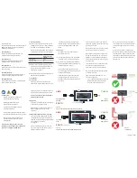
OVR TN Series
Brand: ABB Pages: 2

OVRHS3 Series
Brand: ABB Pages: 8

OVRHMSU Series
Brand: ABB Pages: 6

PW800G
Brand: LG Pages: 29

RD-JT90
Brand: LG Pages: 38

PW600G
Brand: LG Pages: 79

Minibeam UST
Brand: LG Pages: 122


