1 DD860 DIGITAL DEMODULATOR
TM
CONTROLS, INDICATORS AND CONNECTIONS 2
DIGITAL DEMODULATOR
CHANNEL
LOCK
ERROR
SNR
40 dB
15 dB
DD806
0
4
1
DIGITAL DEMODULATOR
CHANNEL
LOCK
ERROR
SNR
40 dB
15 dB
DD806
0
4
1
DIGITAL DEMODULATOR
CHANNEL
LOCK
ERROR
SNR
40 dB
15 dB
DD806
0
4
1
POWER SUPPLY
PS8
R.L. DRAKE COMPANY
230 INDUSTRIAL DRIVE
FRANKLIN, OHIO 45005 U.S.A.
CUSTOMER SERVICE AND PARTS TELEPHONE: +1 (937) 746-6990
TELEFAX: +1 (937) 743-4576
WORLD WIDE WEB SITE: http://www.rldrake.com
12 POSITION RACK MOUNT POWER SUPPLY
DD860 SATELLITE DEMODULATOR
TM
is a trademark of the R.L. Drake Company
®
is a registered trademark of the R.L. Drake Company
© Copyright 2003 R.L. Drake Company P/N: 3852380A-1-2003 Printed in the U.S.A.
The R.L. Drake model DD860 Digital
Demodulator is a professional quality modular
digital headend component designed to provide
optimum performance for VSB or QAM
demodulation. The DD860 receives an 8 VSB,
16 VSB, 64 QAM, or 256 QAM signal from a
terrestrial broadcast or CATV feed in the 54 to
858 MHz range, and demodulates the signal
providing an MPEG-2 digital transport stream
output.
The DD860 normally provides two 75 Ohm,
serial ASI outputs. A parallel SPI output is
available on special order.
Front panel signal to noise ratio and staus
indicators are provided.
A low phase noise tuner design provides
reliable operation with dense signal constella-
tions such as 256 QAM or 16 VSB.
An NTSC co-channel rejection filter for VSB
modes is incorporated.
A wide range equalizer eliminates multipath
effects.
QAM modes incorporate auto selection of
I
TU
A (DVB) or
I
TU B (DigiCipher
II
)
FEC.
IRC and HRC channel plans are selectable by
moving an internal jumper.
The DD860 is designed to mount in the
DRMM12 rack mounting cage.
RF INPUT
POWER
SPI L
VDS OUTPUT
13
1
25
14
+12 V GND +5 V
ASI TRANSPORT
STREAM OUTPUT
RF INPUT
POWER
SPI L
VDS OUTPUT
13
1
25
14
+12 V GND +5 V
ASI TRANSPORT
STREAM OUTPUT
DIGITAL DEMODULATOR
CHANNEL
LOCK
ERROR
SNR
40 dB
15 dB
DD806
0
4
1
F2
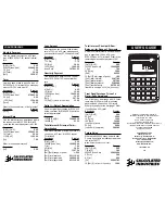
Figure 1
F3
F4
F1 - LOCK
This indicator shows that the demodulator is
receiving a valid digital signal and has locked
to it.
F2 - LED Signal-to-Noise Ratio Meter
Indicates the signal-to-noise ratio of the
received signal. The range is between 15 dB
and 40 dB. Threshold levels are nominally
15 dB for 8VSB, 29 db for 16VSB, 23 db for
64 QAM, and 28dB for for 256QAM. These are
minimum levels required for lock. Normal
operating levels must exceed threshold by
several dB to ensure reliable operation.
F3 - CHANNEL Selector Switch
This switch is used to enter the two or three
digit channel number. The range of numbers is
also used to determine the mode of operation.
F4 - ERROR
This indicator shows that the FEC is not able to
correct all errors in the received signal. Check
for a low signal-to-noise ratio or improper
antenna aiming if errors occur.
FRONT PANEL CONTROLS AND
INDICATORS
R1
R2
R1 - RF INPUT
This "F" type connector is the input for the
tuner. The DD860 will tune to all U.S.A. off air
broadcast frequencies or to standard EIA CATV
channels up to 858 MHz (channel 134).
R2 - DC Power Connector
This is the power input connector. Connect to a
Drake PS8 or equivalent power supply.
R3 - BNC Connectors (ASI output model)
These are the MPEG2 transport stream
outputs. The ASI (Asynchronous Serial
Interface) Output Impedance is 75 Ohms.
R4 - 25 Pin SPI LVDS OUTPUT Connector
(SPI output model)
This is the MPEG2 transport stream output.
The DVB Synchronous Parallel Interface levels
comply with low voltage differential signalling
specifications.
Figure 2 (ASI)
+12V GND +5
REAR PANEL CONNECTIONS
R4
Figure 3 (SPI)
R1
R2
R3
F1