Professional Headend Solutions
Operating instructions
Contents
1. Safety and operating instructions ...................................................................2
2. Device variants .. ..............................................................................................2
3. General ............... .............................................................................................2
4. Front view .........................................................................................................3
5. Function description ........................................................................................3
6. Adjustments ................ ....................................................................................3
6.1 Adjustment with the Headend Controller ..................................................3
6.2 Adjustment with the PC / laptop ................................................................3
7. Meaning of LED signals ...................................................................................4
7.1 LED`s for the ASI ports ............................................................................4
7.2 LED`s on front panel ................................................................................4
8. Optional hardware variants .............................................................................4
8.1 IF interface ... .............................................................................................4
8.2 Additional A/V monitor outputs .................................................................5
9. Programming by Web server ..........................................................................6
9.1 Main menu ..............................................................................................6
9.2 Software options .......................................................................................6
9.3 Loading the programme list ......................................................................7
9.4 Extended settings .....................................................................................8
9.5 Manual settings ........................................................................................9
9.6 Factory settings .........................................................................................9
9.7 Status of device ......................................................................................10
10. Manual menu control at the Headend Controller .......................................11
11. Trap messages . ...........................................................................................11
12. Block diagram ............................................................................................12
13. Head end BUS structure ..............................................................................12
14. Example of use ............................................................................................13
15. Technical data .. ...........................................................................................13
16. Glossary .............................. ........................................................................14
17. Bibliography ..... ...........................................................................................14
18. History ................ .........................................................................................14
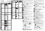
ATB 19x
Part N
o
: 9848.xx
ASI - TV Transmodulator
ASI
→
ATV (AM)