background image

INSTALLATION SHEET

7000 Series Thinline LCD Keypads

Models 7060/7063/7070/7073

Description

The DMP Model 7060, 7063, 7070, and 7073 Thinline LCD Keypads offer the same flexible features and functionality 

as current DMP keypads in a stylish, sleek new design.  Each keypad provides four 2-button Panic keys, AC power 

LED, Armed LED, 32-character display, backlit logo and keyboard with easy-to-read lettering and an internal speaker.  

In addition, the Models 7070 and 7073 keypads also provide four fully programmable Class B, Style A protection zones 

you can program for a variety of burglary and access control applications.  
The Model 7063 and 7073 keypads provide a built-in proximity card reader designed to read HID 1300 Series and DMP 

1400 Series proximity credentials.  The Model 7073 keypad also provides a door strike relay and allows Wiegand input 

from HID, DMP, or other external card readers.

Installing the Keypad

The keypad housing is designed to easily install on any 4” square box, 3-gang switch box, DMP 695 and 696 backbox, 

or a flat surface.  Figure 1 shows the keypad housing mounting hole locations.
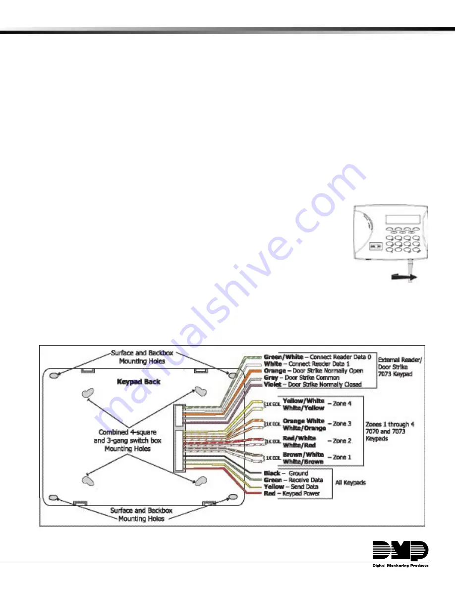
Removing the Base

The keypad housing is made up of two parts: the front, which contains the circuit board, 

keyboard components, and the base.  To remove the base, insert a flat screwdriver into one 

of the openings on the bottom and twist the screwdriver while pulling the halves apart.  

Repeat with the other opening.

Harness Wiring

Figure 1 shows wiring harness assignments.  Observe wire colors when connecting the 

red, yellow, green, and black wires to the keypad bus.  When wiring directly to the panel 

terminals, connect red to panel terminal 7, yellow to terminal 8, green to 9, and black to 

panel terminal 10.  Use 1k Ohm EOL resistors, DMP Model 311, on keypad zones 1 through 4. 
The 7060 and 7063 keypads are supplied with a 4-wire harness for panel keypad bus connection.  
The 7070 and 7073 keypads are supplied with a 12-wire data bus/zone harness.  Four wires connect to the keypad 

bus.  The remaining eight wires are for the four zone inputs: two wires for each zone.  
The 7073 keypad is also supplied with one 5-wire output/reader harness.

Figure 1: Keypad Back Showing Wiring Harness Assignments

Содержание Thinline 7060

Страница 1: ... switch box DMP 695 and 696 backbox or a flat surface Figure 1 shows the keypad housing mounting hole locations Removing the Base The keypad housing is made up of two parts the front which contains the circuit board keyboard components and the base To remove the base insert a flat screwdriver into one of the openings on the bottom and twist the screwdriver while pulling the halves apart Repeat wit...

Страница 2: ...nel output you can provide additional current by adding a Model 505 12 auxiliary power supply Connect all keypad black ground wires to the power supply negative terminal Run a jumper wire from the power supply negative terminal to the panel common ground terminal Connect all keypad power 12 VDC wires to the power supply positive terminal Do NOT connect the power supply positive terminal to any pan...

Страница 3: ...el the keypad door strike relay activates for 5 seconds During this time the access door connected to zone 2 must be opened to start the 40 second entry exit timer and zone Soft Shunt See the timeline shown below Note The 5 second door strike is programmable when the keypad is used on an XR200 485 XR500 Series or XR2500F panel Refer to the XR500 Series Programming Guide LT 0679 or the XR200 485 Pr...

Страница 4: ...on Panic left two Select keys Zone 19 Device Address Emergency non medical center two Select keys Zone 29 Device Address Fire right two Select keys Zone 39 Device Address Figure 5 Panic key label placement 7 0 Panic Keys The 7000 Series keypads also allow the user to initiate a Panic alarm by pressing the 7 and 0 zero keys simultaneously for one half 1 2 second You must enable the 7 0 Panic functi...

Страница 5: ...uble conditions the volume is always at maximum level Use the left Select key to decrease the keypad volume and the right Select key to increase the volume Press the CMD key to display the Model Number MODEL NUMBER 7073 V201 030804 Model Number The LCD displays the keypad model number and the keypad firmware version and date The user cannot change this information in User Options KEYPAD ADDRESS 01...

Страница 6: ...P UNSUP Keypad Mode Configure the keypad for either supervised or unsupervised operation Keypads with zones connected to them must be supervised Supervised keypads cannot share addresses with other keypads Unsupervised keypads can operate with other unsupervised keypads sharing the same address Zones cannot be used on unsupervised keypads To change the current setting press the Select key under SU...

Страница 7: ...resented for arming the Home Sleep Away system After a card is presented HOME SLEEP AWAY displays The keypad waits the programmed number of seconds before automatically selecting AWAY Accessing Keypad Diagnostics If necessary refer to Access the Installer Menu on the previous page KPD KPD OPT DIAG STOP Keypad Diagnostics KPD DIAG The Keypad Diagnostic option allows you to check the display segment...

Страница 8: ...lay present the credential to the reader The keypad works by reading the 4 or 5 digit user code from the data sent by the access control reader For more information refer to Entry Cards in the programming section of this document and the following User s Guide section on adding deleting and changing user codes 7063 and 7073 User s Guide There are three different sections Keypad Arming and Disarmin...

Страница 9: ...are disarmed If the system is disarmed when you present your card once the card is validated all areas are armed in the AWAY mode Keypad Door Strike Area and All Perimeter Door Strike From the Status List present your card to the reader Once the system validates the card the Door Strike relay activates Home Away systems only activate the Door Strike relay when arming and disarming Figure 10 Presen...

Страница 10: ... X FCC Information This device complies with Part 15 of the FCC Rules Operation is subject to the following two conditions 1 This device may not cause harmful interference and 2 this device must accept any interference received including interference that may cause undesired operation Changes or modifications made by the user and not expressly approved by the party responsible for compliance could...

Отзывы: