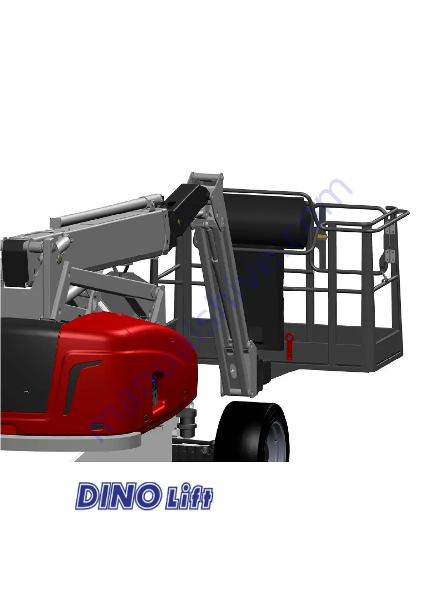
background image


DINO


®

 185XTS


OPERATING INSTRUCTIONS 

Dealer

:


Manufacturer

Raikkolantie 145 
FI-32210 LOIMAA 
T. +358 2 762 5900 
F. +358 2 762 7160 
[email protected] 
www.dinolift.com 


Summary of Contents for DINO 185XTS

Page 1: ...DINO 185XTS OPERATING INSTRUCTIONS Dealer Manufacturer Raikkolantie 145 FI 32210 LOIMAA T 358 2 762 5900 F 358 2 762 7160 dino dinolift com www dinolift com ...

Page 2: ...2 ...

Page 3: ...3 ORIGINAL OPERATING INSTRUCTIONS VALID FROM SERIAL NUMBER 540016 ...

Page 4: ... THE STABILITY 27 12 STARTING UP 28 12 1 Familiarise yourself with the machine and these instructions 28 12 2 Starting the engine 28 12 2 1 From the chassis control panel LCB 28 12 2 2 From the platform control panel UCB 29 12 3 Transferring driving and steering 31 12 3 1 Driving to the front and to the rear 31 12 3 2 Steering 32 12 3 3 Using the differential lock 32 12 4 Operating the boom 32 12 ...

Page 5: ... servicing 59 26 2 1 Cleaning the lift 59 26 2 2 Changing the hydraulic oil and the filters 60 26 2 3 Hydraulic hoses connectors and pipes 62 26 2 4 Chassis transmission axles and wheels 62 26 2 5 Checking the boom cylinders 63 26 2 6 Inspecting the boom and the chassis 64 26 2 7 Checking the operation of the load control system for the platform MRV 68 26 2 8 Measuring the pressure 70 26 2 9 Check...

Page 6: ...r the transmission 87 29 2 Fault finding table 88 30 DIAGRAMS AND COMPONENTS 92 30 1 ELECTRIC SAFETY COMPONENTS 540001 92 30 1 1 CHASSIS CONTROL CENTRE LCB RELAYS 92 30 1 2 CHASSIS CONTROL CENTRE LCB SWITCHES 92 30 1 3 CONTROL CENTRE ON PLATFORM UCB SWITCHES AND SIGNAL LIGHTS 92 30 1 4 LIMIT SWITCHES AND SAFETY DEVICES 93 30 1 5 OTHER MARKINGS 94 30 2 DINO 185 XTC ELECTRIC COMPONENTS 540003 95 30 ...

Page 7: ... and also fulfils the requirements of the following EEC directives Low Voltage Directive 2006 95 EC directive 2000 14 EC and EMC Directive 2004 108 EC Conformity assessment procedure followed 2000 14 EC Annex V Internal control of production Measured sound power level Lwa 95 5 1 5 97 dB Quaranteed sound power level Lwa 97 0 5 dB Notified body nr 0044 RWTÜV Postfach 10 32 61 DE 45032 Essen has gran...

Page 8: ...8 2 REACH DIAGRAM ...

Page 9: ...9 3 DIMENSION DRAWING ...

Page 10: ...llowed sideways load caused by persons 400 N Max lateral inclination of chassis 5 Max wind speed during operation 12 5 m s Min ambient temperature when working 20 C Tyres IN315 55D20 Foam filling Maximum possible tyre load 35 000 N 3 570 kg Max ground pressure 3 2 kg cm2 Platform size 0 8 x 1 8 m Driving speed high low 1 km h 6 km h Gradeability 45 Power supply DIESEL Combustion engine Deutz D2011...

Page 11: ...on this page Left Turning counter clockwise Platform Axle Boom extension 1 Boom extension 2 Boom extension 3 Right Turning clockwise Levelling cylinder of platform Articulated arms Boom cylinder Lifting cylinder Turning device Arm cylinder Mastercylinder Chassis Boom support Locking cylinder Jib cylinder Jib Chassis control centre LCB Platform control centre UCB ...

Page 12: ...onnel with authorisation in writing from their employer and who have good familiarity with the device and are at least 18 years old are allowed to operate the lift The max allowed load on the platform is two 2 persons and at maximum ninety 90 kg of additional load however the total load must not exceed two hundred fifty 250 kg The work platform may only be used whilst the chassis is well supported...

Page 13: ...r safe operation and impede the inspection of the structures The device must be serviced and inspected regularly Only skilled persons familiar with servicing and repair instructions are allowed to carry out servicing and repair work It is strictly prohibited to use a lift which is out of order The lift must not be used when located on the bed of a lorry on a trailer on board a vessel or in any oth...

Page 14: ...n Before starting the operation always ensure that the safety devices and the emergency descent system are working properly Do not take tools material of large surface area onto the platform The increase in wind load may jeopardize the stability of the device Always keep the lift free from dirt snow and ice Ensure that the lift is inspected and serviced before use Never use a defective lift Never ...

Page 15: ...r all such specific work methods or conditions that the manufacturer has not explicitly defined Beware of the live aerial power lines in the area observe the minimum safety distances Use a safety harness while on the platform Weight Min distance below m Min distance at the side m 100 400 V hanging spiral cable 0 5 0 5 100 400 V open wire cable 2 2 6 45 kV 2 3 110 kV 3 5 220 kV 4 5 400 kV 5 5 Fixin...

Page 16: ...ous inspection If the lift is used under extreme conditions intervals between the inspections shall be reduced The overall operating condition of the lift as well as the condition of the safety related control devices shall be established in the regular inspections Particular attention shall be paid to changes which affect the operational safety In connection with the regular inspection it shall b...

Page 17: ...control panels see point Emergency descent system Testing the sound signal and the signal lights Check that the lights and reflectors are in order and clean and the warning and instruction decals are clean Check the condition of the operating controls and test all the work movements Check the condition of the access routes the platform gate and the handrails Check the operation of the safety devic...

Page 18: ... system for platform load Check that when there is no load on the platform both the green and the yellow LED indicators are illuminated see point Operation of the safety devices Check the element of the Diesel engine cooler for cleanliness ...

Page 19: ... and have the defects affecting the safety been checked as repaired Inspection protocols 3 Structure Visual inspection and operational test General condition of the lift Operation and protection of the controls Emergency stop signal horn and limit switches Electrical appliances and wiring Oil leaks Load markings and signs 4 Operator Is the operator old enough Has the operator received the required...

Page 20: ...oom extensions is extended The switch is located at the rear end of the 1st boom behind the boom end cover Test the operation by making a driving speed test with the lever S22 in the high position the boom extensions at first fully retracted and then slightly extended Only the low speed must operate while the boom extensions are extended 9 3 Emergency stop buttons S1 and S4 Stops all the movements...

Page 21: ...e load control system turns off the power unit when the work platform collides with an obstacle the work platform shall be transferred away the collision point using the emergency descent system Then the overload situation will be reset and the normal operation of the lift will resume Table alarm from the platform load control device Weight Signal light H19 Sound signal Boom control 245 265kg On N...

Page 22: ...D Green Power on illuminated in operation flashes o When the power is turned on the green LED is illuminated o Once the sensor is activated the Green LED starts flashing The operation of the platform load control device is checked via the LED signal lights When the work platform is unloaded and is not in contact with any external structure the Orange signal light must be illuminated and the Green ...

Page 23: ...uring sensor for inclination allows the unit to be turned only in the safe direction The inclination is indicated by the signal lights H23 and H24 in the UCB centre The correct operation of the inclination control is tested by driving the lift uphill to an angle of 5 to be established by measuring If the boom system is moved from its transport position the transfer of the lift will be prevented an...

Page 24: ...ht HM1 Hourmeter Q1 Power switch S1 Emergency stop button DPF Signal light The Diesel particle filter needs to be replaced S6 Start stop engine S14 Operating switch for emergency descent system S16 Turning the boom S17 Lifting and lowering the boom S18 Boom extensions in out S19 Lifting and lowering the articulated arms S20 Levelling the platform forward backward S21 Jib arms up down S22 Swing of ...

Page 25: ...on counter clockwise H30 Control system failure Diesel engine JSL Control lever for boom JSR Operating lever for transfer drive JS2 Lifting and lowering the articulated arms JS3 Boom extensions in and out JS4 Lifting and lowering the jib arms S4 Emergency stop button S5 Start stop engine S10 Sound signal S11 Emergency descent S12 Inclination of work platform S22 Transfer speed range slow fast S32 ...

Page 26: ...trol lever for boom JSR control lever for driving DMS1 Foot pedal on the platform dead man switch Turning the boom clockwise counter clockwise Boom Lifting lowering DMS1 Drive Forward Backward Turning the wheels ...

Page 27: ...oom If the stability has been lost as a result of a fault in the lift repair such a fault immediately Do not use the lift until the fault has been repaired and the condition of the lift has been verified IN CASE OF OVERLOADING The engine shuts down and the movements stop the red signal light H17 is flashing and the buzzer sounds intermittently 1 If there is time try to find out the reason for the ...

Page 28: ...hine and these instructions Read these instructions carefully and check out the warning and instruction decals affixed to the machine before starting the operation 12 2 Starting the engine 12 2 1 From the chassis control panel LCB 1 Familiarise yourself with the switches and lights mentioned in this chapter in point LCB operating controls in the chassis panel XTS 2 Perform the daily inspection see...

Page 29: ...ontrols in the platform panel XTS 2 Perform the daily inspection see point Daily inspection start up inspection 3 Perform the worksite inspection see point Worksite inspection 4 Make sure that the mains switch BMS is turned on and that the emergency stop buttons S1 and S4 have been pulled up 5 Turn the power switch Q1 in the LCB panel to the right to position Platform control panel Take the keys w...

Page 30: ...esel engine is running If any of the warning lights remains illuminated turn off the engine and find out the reason Repair the faults before re start If the signal light H29 or H30 for the control system of the Diesel engine remains illuminated or flashes contact the service personnel The signal lights H30 or H29 indicate the following o function test turn the power on the light shall remain lit f...

Page 31: ...e transferring the lift With the work platform raised the inclination must not exceed 5 With the work platform in the transport position the inclination must not exceed 20 Exercise extreme caution when driving with the work platform raised Transfer of the lift is only possible from the UCB panel on the platform The turning device and the jib arms can be operated during transport driving The oscill...

Page 32: ...urned in the desired direction of travel by depressing the switches at the end of the transport driving lever JSR NOTE The turning direction of the wheels will change if the turning device is reversed with respect to the chassis The turning direction of the wheels will however not be changed until the control switch is released and pressed again The change of direction takes place when the turning...

Page 33: ...tend the boom extensions 1 2 metres JS3 up and depress the emergency stop button the engine and the movement should now stop 2 Start the emergency descent unit pushbutton S13 retract the telescope lever switch S18 or pushbutton S32 and lower the boom lever switch S17 3 Pull up the emergency stop button NOTE The boom movements are noticeably slower when the emergency descent system is used NOTE Rem...

Page 34: ...p down Articulated arms up down Stepless adjustment JS3 up down Boom extensions in out Stepless adjustment JS4 up down Jib arms up down Stepless adjustment S36 to the left right Turning the platform clockwise counter clockwise Constant speed S12 up down Levelling of the platform Constant speed ...

Page 35: ...ements operate as described in the following table Figure Lever Movement Movement speed S16 to the left right Turning device clockwise counter clockwise Slow fast S17 up down Boom up down Slow fast S18 up down Boom extensions in out Slow fast S19 up down Articulated arms up down Slow fast S20 up down Levelling of the platform up down Slow fast S21 to the left right Jib arms up down Slow fast S22 t...

Page 36: ...AT THE POWER SUPPLY CABLE DOES NOT GET UNDER THE TYRE OR CLING TO ANY OBSTACLE WHEN TRANSFERRING THE LIFT 12 6 General driving instructions 1 Refer to the item Daily inspections in the task list for servicing 2 With the boom slightly lifted and the telescope extended make sure that the platform does not lower by itself while the operating controls are not being used 3 When working under cold weath...

Page 37: ...the same position It is however recommended to let the combustion engine run now and again between the operations to ensure that the battery remains well charged Check the condition of the lift s standing base regularly during the operation taking into account the weather and the properties of the terrain 8 When moving the platform remember the following Beware of high voltage lines see the safe d...

Page 38: ...85 Ah battery charger 230 VAC OPTION battery charger Diesel emergency power unit 12VDC 2 Servicing the battery the system incorporates an automatic battery recharger with short circuit and overheat protection if necessary top up distilled water above the battery elements 3 The hydraulic unit comprises pressure relief valve set value 17 MPa 170 bar check valve direct current motor 12 VDC 800 W The ...

Page 39: ...ib arms using the operating levers 4 At first retract the telescope using the emergency descent system then lower the booms NOTE If the emergency descent system does not operate try to warn other personnel present on the site so that they can make the lift engine or the emergency descent unit operational by for example changing the battery or feeding auxiliary current to the battery NOTE Always ch...

Page 40: ...ever they are not in use ALWAYS KEEP THE LIFT FREE FROM DIRT SNOW ICE ETC 15 MEASURES TO BE TAKEN AT THE END OF THE WORKING DAY 1 Drive the machine to a safe and level surface for parking If necessary use chocks 2 Retract the boom extensions completely and bring the boom into the transport position In the transport position the boom extensions are fully retracted the boom is at its lowest position...

Page 41: ... the work platform to prevent the platform from contacting the ground 2 Turn off the electric system by turning the switch Q1 in the LCB centre to the middle position 0 and turn the mains switch BMS to the position 0 3 Make sure that the boom is parallel to the chassis 4 When transporting the lift on a lorry the engine should point in the driving direction 5 Drive the unit or lift it onto the tran...

Page 42: ...e device is allowed by the designated points only There are marked lifting lugs on the chassis 4 pcs and in the turning device 2 pcs The total weight of the lift is 8 000 kg Use only lifting gear intended for the purpose Be careful not to damage the lift s boom during lifting Lift in the transport position only Lifting lug Load binding lug ...

Page 43: ...port position using the emergency descent system o To release the brakes manually unscrew the bolts 4 pcs in the solid axle as much as is required to be able to remove the U washers After this tighten the bolts all the way to release the brakes o Chock the wheels to prevent the lift from coasting The brakes must not be released on a gradient o Switch the pump to free circulation by unscrewing the ...

Page 44: ... CIRCULATION OF THE PUMP BY TIGHTENING THE BOLTS 2 PCS In the event of emergency if an obstacle prevents the boom from being driven to the transport position exercising particular caution and avoiding abrupt movements tow the unit to a place where the boom can be lowered to the transport position Washer Bolt X4 RELEASING THE PUMP FOR TOWING ...

Page 45: ...45 17 NOTES ...

Page 46: ... the manufacturer Any faults that may affect the operational safety of the unit must be repaired before the lift is next used Do not let oil spill on the ground Keep the lift clean especially the platform Clean up the lift before service and inspection Only use genuine spare parts Support the platform boom system articulated arms and support outriggers in a position in which the load does not rest...

Page 47: ... 3 Weekly service Lubricate the joint pins see point Lubrication plan Check the engine oil level Check the sliding surfaces of the telescope and apply silicon if necessary Check the clearance between the slide pads and surfaces and adjust the pads if necessary Check the operation of the platform load control see point Control system for platform load 4 Service every six months Change the hydraulic...

Page 48: ...IODIC SERVICING AND THE INSPECTIONS IS ABSOLUTELY MANDATORY BECAUSE THEIR NEGLIGENCE MAY IMPAIR THE OPERATIONAL SAFETY OF THE LIFT NOTE THE GUARANTEE WILL NOT REMAIN VALID IF THE SERVICING AND THE PERIODIC INSPECTIONS ARE NOT PERFORMED ...

Page 49: ...49 Obscured greasing nipples 19 LUBRICATION INSTRUCTIONS ...

Page 50: ...f platform levelling cylinder 2 X ESSO Beacon EP2 4 Bearings of jib cylinder 2 X ESSO Beacon EP2 5 Bearings of jib arms 8 X ESSO Beacon EP2 6 Bearings of boom cylinder 1 X ESSO Beacon EP2 7 Bearings of platform levelling cylinder 2 X ESSO Beacon EP2 8 Bearings of articulated arms 21 X ESSO Beacon EP2 9 Bearings of articulated arm cylinders 4 X ESSO Beacon EP2 10 Articulation bearings of axle oscil...

Page 51: ...ps described in the instructions see point Inspections 21 AXLES AND TYRES NOTE THE TYRES ARE FILLED WITH FOAM NO INFLATION WITH AIR 21 1 Tightening torques of the bolts Tightening torque of the wheel bolts 360 Nm M18 32 pcs Tightening torque of the steering axle s attachment bolts 520 Nm M20 2 pcs Tightening torque of the fixed axle s U bolts 230 Nm M20 2 pcs Tightening torque of the oscillating a...

Page 52: ...ferential lock Friction lock 45 Lockable 100 N A Reduction gear 1 2 28 N A N A Differential 8 35 8 35 N A Planetary gear 1 6 1 6 N A Reduction gear oil SAE85W90 API GL 5 SAE85W90 API GL 5 Change interval 1000 h Differential oil SAE85W90 API GL 5 SAE85W90 API GL 5 Change interval 800 h Planetary gear oil SAE85W90 API GL 5 SAE85W90 API GL 5 Change interval 1000 h Brakes Internal brake self adjusting...

Page 53: ...f the arms cylinder levelling cylinder Load regulation valve of the boom cylinder Load regulation valve of the jib cylinder oscillation Oscillation lock of the axle load regulation valve 22 LOAD HOLDING AND LOAD REGULATION VALVES 22 1 Location of the load regulation valves ...

Page 54: ...ew minutes and check whether the wheel has stayed off the ground Drive again the boom parallel to the chassis When the boom is again parallel to the chassis the oscillation of the axle will be released and the wheel will lower to the ground Repeat the test also with the other wheel of the oscillating axle See point Location of the load regulation valves Checking the operation tightness of the load...

Page 55: ...NDER REPAIR SERVICED MAKE SURE TO RELIEVE THE RESIDUAL PRESSURE FROM THE CYLINDERS DO NOT LET OIL SPILL ON THE GROUND PROTECT YOUR SKIN AGAINST THE HYDRAULIC OIL 1 Carefully support the structure that is being serviced and make sure that the residual pressure has been relieved from the relevant cylinder 2 Remove and clean the valve 3 Check the O rings and replace if necessary 4 Put the valves care...

Page 56: ... on the piston rod side in the direction of the electric directional valve which is not tight 2 an internal leakage in the cylinder If the platform viewed by the operator tilts backwards the reason can be 1 a leak in the load regulation valve part 2 on the piston bottom side of the slave cylinder in the direction of the electric directional valve which is not tight 2 an internal leakage in the cyl...

Page 57: ...the user interface connector shown in the picture 4 Connect the conductor of the TEACH IN tool to the socket Dino id 48 19044 5 The letter T starts to flash in the adjusting device 6 Keep the button marked 4 depressed for about 4 seconds until the letter T will be illuminated continuously When you release the button the letter T will flash slowly 7 Place a weight of 285 kg in the middle of the pla...

Page 58: ...he adjustment of the platform load control is now completed If the platform load exceeds 285 kg then the platform load sensor switches off the power unit and prevents all the movements In this situation the buzzer will sound intermittently and the red signal light will flash The emergency descent functions of the lift operate normally 25 DPF DIESEL PARTICLE FILTER OPTION The change interval of the...

Page 59: ...dealer 26 2 Schedule for regular servicing 26 2 1 Cleaning the lift Clean the lift thoroughly before the service It is important that the hydraulic or electric components should not be opened if they are dirty Any contaminants in the system may cause malfunctions later on Water and a suitable solvent detergent shall be used for washing externally o NOTEBe careful not to direct the high pressure wa...

Page 60: ...6 litres o Factory filling Mobil EAL 32 o The viscosity class of the hydraulic oil must be ISO VG32 and the oil must comply with DIN 51524 HLP o Material Safety Data Sheet EXXON MOBIL no 581017 60 o NOTE Never mix different types of oil o NOTE Do not spill oil into the natural environment You can top up oil either via the cap on the return filter or via the quick connector next to the return filte...

Page 61: ... for reserve power unit Draining oil from the tank Return filter and filling cap of the oil tank Pressure filter Quick connector filling hydraulic Oil Refill filter for drive hydraulics Sight glass for oil level ...

Page 62: ...tightness 230 Nm M20 2 pcs Check the tightening torque of the bolts for the oscillating axle s locking cylinder 62 Nm M12 8 pcs 26 2 4 2 Check the wheels Check the condition of the tyres wear possible cracks and tears Check the rims welded seams crack and distortions The tyres are filled with foam NO INFLATION WITH AIR 26 2 4 3 Check the play of the joints of the steering axle and the transmission...

Page 63: ... in any position 4 Lubricate all joints 5 Check the operation of the load regulation valves see point Load regulation valves Extend and retract the cylinder of the arms from the operating controls on the chassis control panel LCB Perform the above checks according to points 1 5 Extend and retract the boom cylinder from the operating controls on the chassis control panel LCB Perform the above check...

Page 64: ...and retracting chains of the boom for tightness See the picture on the next page The slide pads of the boom extensions must be lubricated and adjusted according to the instructions 1 Drive the boom to a level position 2 Extend the boom extensions completely and after that retract them about 30 mm 3 Check that the extending chain closer to the limit switch in the picture green does not hang notably...

Page 65: ...nt Return the boom extensions to the measuring position and repeat the measurement Check the attachment of the unloaded chain in the picture red by pulling it with your hand CHECKING AND ADJUSTING THE TIGHTNESS OF THE BOOM EXTENSIONS EXTENDING AND RETRACTING CHAINS Limit switch ...

Page 66: ...ss Check the axial play of the turning bearing The play must not exceed 1 mm NOTE If you have to turn open or tighten the attachment bolts do not forget to use bonding adhesive tighten crosswise 26 2 6 4 Checking the limit switches Check the attachment cleanliness and externally the condition of the limit switches Also pay attention to the condition of the limit switch covers and conductors Safety...

Page 67: ...platform MRV Safety limit switches on the turning device 2 pcs o Sensor for the turning device position RK2 o Measuring sensors for inclination RK30a and RK30B MRV RK7 RK3 RK16 RK8 RK18 Location of the limit switches RK30a RK30b RK2 Location of the safety limit switches ...

Page 68: ...atform Beware of damaging the structure of the work platform or the controls The signal light in the UCB centre H19 must remain illuminated continuously The movements of the lift shall operate normally 5 Add a load of about 35 kg 77 lbs onto the work platform The total load on the platform rises to 285 kg 628 lbs The signal light H19 in the UCB centre must flash The sound signal must alarm intermi...

Page 69: ...is flashing and the ORANGE LED is continuously illuminated If the load control system for the platform does not operate properly the sensor must be calibrated by means of the TEACH IN tool Contact a service workshop that is well familiar with the subject or the seller of the lift See the point Calibration of the control sensor for the platform load for instructions ...

Page 70: ...essure of the different boom movements in accordance with the adjacent table by driving the cylinder for the respective movement against its external position in the direction to be measured Measuring object measuring point Max Pressure Movement to be measured Main pressure max pressure 1 210 bar Boom extensions in Turning device 3A 3B 80 bar Turning device counter clockwise clockwise Boom extensi...

Page 71: ...e of damaging the cooler 1 After every 1000 h or at least once a year refer to the operating instructions for the engine that are included in the delivery for more detailed information Change the engine oil and the oil filter every 1000 hours or once a year o Mobil Delvac MX extra 10W 40 API CI 4 CH 4 CG 4 CF SL SJ or equivalent o filling capacity with without air filter 5 5 6 l 2 After every 1000...

Page 72: ...ons for the engine that are included in the delivery for more detailed information Replace the V belt Replace the glow plug Engine oil filter Fuel filter Pre filter water trap for fuel Drain screw in water trap Battery Main fuse Deutz location of service objects ...

Page 73: ... the box type structures with anti corrosion coating and renew the treatment if necessary using e g Tectyl 210R anti corrosive agent 26 2 13 Test run in accordance with the loading instructions See the relevant test run instructions in point Test loading instructions for regular inspection Check the structures after the test run 26 2 14 Draw up a protocol of the service Save your own copy and give...

Page 74: ...tform load control see point Regular servicing Checking the operation of the load control system for the platform MRV 11 Check the locking of the oscillating axle see point Checking the operation of the load regulation valves After the above mentioned test loadings and the subsequent inspection have been completed without finding any defects in the structure or stability of the lift the lift may b...

Page 75: ...75 NOTES ...

Page 76: ...a work site shall be subjected to a regular maintenance inspection if possible once a week Keep a journal of any notable shortcomings and defects observed and advise the foreman of them 28 1 FIRST INSPECTION The initial inspection and test loading of the Dino access platforms is performed by the manufacturer A protocol which accompanies the lift is drawn up of the inspection ...

Page 77: ...77 28 1 1 Sample of inspection protocol for the access platform Continuous ...

Page 78: ...78 ...

Page 79: ... drift see point Checking the operation of the load regulation valves 6 Check the locking of the oscillating axle see point Checking the operation of the load regulation valves 7 Check the level of hydraulic oil in the sight glass with the boom system in the transport position 8 Check the level of the Diesel engine oil with the dipstick 9 Electro hydraulic rotary adapter check that there are no oi...

Page 80: ...r does not harm the environment For example dry the electric or hydraulic components that you intend to open by blowing compressed air over them Apply appropriate moisture repellent to the electric appliances after the drying The piston rods must always be protected with CRC3 36 anti corrosive agent after washing with a solvent or equivalent 28 3 1 Perform the measures of the daily and monthly ins...

Page 81: ...utiny that they all are functioning properly and that the movements stop as soon as the levers are released Electric directional valves on the chassis Check that the valves for the steering of wheels the brake and the locking of axle oscillation are operating properly and no movements will be executed after releasing the levers Electro hydraulic rotary adaptor Check that the adaptor does not show ...

Page 82: ...eck the condition and protection against moisture of the cable connections Signal lights and buzzers Check the operation and visibility of the signal light Check the operation of the buzzer Limit switches Check the operation of the limit switches Check the condition attachment and protection of the limit switches Check that the lead throughs of the limit switches are tight Valves Check the conditi...

Page 83: ...king of the pins Check the condition of the joint pins and bearings of the jib arms and the locking of the pins Inspecting the boom Extend the telescope and check that there are no permanent deformations dents or traces of substantial wear in the boom Also check that the welded seams neither are worn nor show cracks or breaches Check the condition of the boom brackets for cracks or breaches Check ...

Page 84: ...motor Checking the transmission General condition Check the wheel bolts for tightness Visually check the condition of the tyres wear and cracks Check the attachment bolts of the axles for tightness Check the steel structures next to the attachment points of the axles and the welded seams for breaches and traces of corrosion Check that the joints of the axles are free of play Operational tests Test...

Page 85: ...ft is ready for operation after the annual inspection the date of inspection shall be marked on the inspection plate affixed to the lift 28 4 EXTRAORDINARY INSPECTION INSPECTION AFTER AN EXCEPTIONAL SITUATION The inspection is required if the lift has been damaged in a manner which may affect its load bearing capacity or safe operation thus the lift shall be inspected according to the instructions...

Page 86: ...ode is 0 5 The second digit of the code i e the number of fast flashes in the example 4 flashes 6 The pause after which restart from point 1 In the example the error code is 34 29 1 1 Error codes of the control system for the boom The error codes of the control system for the boom will not be shown unless the control lever is shifted in the proper direction the pedal DMS1 is being depressed and th...

Page 87: ... FLASH CODE BEING SHOWN IS NOT PRESENTED IN THE TABLE CONTACT A SERVICE PROVIDER WHO IS VERY FAMILIAR WITH THE LIFT IN THE CASE OF FAILURE CONTACT A SERVICE PROVIDER WHO IS FAMILIAR WITH THE LIFT Code Digits Fault IIII 11 The battery voltage will be monitored IIII 13 internal reference voltage failed IIII 14 Analogue injection channel IIII 15 Watchdog IIII 16 Sensor voltage error nominal 5 V IIII ...

Page 88: ... RK7 for retraction of boom extensions has disconnected the contactor circuit Check the operation of the RK7 and readjust See point Regular servicing Checking the extending and retracting chains of the boom for tightness The safety relay SR4 is not automatically reset With reference to electric diagrams check the operation of the safety relay 3 Engine cranks but does not start Fuel tank is empty F...

Page 89: ... Fuses are in the control centre LCB replace the fuse 6 Disturbance of platform movements only one of the movements is operational During driving the following movements are prevented Lifting lowering the boom Retracting extending the telescope Lifting lowering the articulated arms Stop and retry When operating from the platform check whether a flashing code is active In accordance with the code c...

Page 90: ... spool The lift turns when the lifting movement is activated Solenoid valve is stuck in turning position Wash carefully the spool and the block 9 Telescope movement does not operate Refer to item 6 Check that the solenoid valve of the telescope is not stuck in the centre or in the lowering position 10 Telescope retracts slowly The load regulation valve leaks For remedy refer to item 7 11 Platform ...

Page 91: ... light and the buzzer raise the alarm Lower the boom onto the support retract the boom extensions completely The following boom movements prevent driving Lifting lowering the boom Retracting extending the telescope Lifting lowering the articulated arms Stop using the boom and drive the boom system to the transport position Check whether a flashing code is active Check if a flashing code is active ...

Page 92: ... inclination of the lift exceeds 5 degrees The safety relay operates if the inclination is less than 5 degrees or the boom is resting on the support and the telescope is fully retracted The safety relay is released when the inclination exceeds 5 degrees and the boom has been raised or the telescope has been extended 30 1 2 CHASSIS CONTROL CENTRE LCB SWITCHES S1 LOCKING EMERGENCY STOP SWITCH Stops ...

Page 93: ...xceeds 5 degrees RK7 SAFETY LIMIT SWITCH FOR THE TELESCOPE CHAIN The safety limit switch disconnects the emergency stop circuit after which only the emergency descent unit remains operational RK8 TELESCOPE IN THE INNER POSITION SAFETY LIMIT SWITCH Limits the driving speed while the telescope is extended Prevents the operation of the drive system while the telescope is extended and the inclination ...

Page 94: ... by buzzer H18 and flashing of signal light H19 in the event of overloading 30 1 5 OTHER MARKINGS M2 EMERGENCY DESCENT MOTOR 12VDC MAX OPERATING TIME 10 MIN SR1 Solenoid for the emergency descent unit When energized starts the emergency descent unit M2 BMS Mains switch Disconnects the plus terminal of the battery RCD FAULT CURRENT SWITCH 25 A 30 ms ÄM1 SOUND SIGNAL ...

Page 95: ...95 30 2 DINO 185 XTC ELECTRIC COMPONENTS 540003 30 3 ...

Page 96: ...96 ...

Page 97: ...97 ELECTRIC DIAGRAMS 540003 ...

Page 98: ...98 ...

Page 99: ...99 ...

Page 100: ...100 ...

Page 101: ...101 ...

Page 102: ...102 ...

Page 103: ...103 ...

Page 104: ...104 ...

Page 105: ...105 ...

Page 106: ...106 ...

Page 107: ...107 ...

Page 108: ...108 ...

Page 109: ...109 ...

Page 110: ...110 ...

Page 111: ...111 ...

Page 112: ...112 ...

Page 113: ...113 ...

Page 114: ...114 ...

Page 115: ...115 ...

Page 116: ...116 ...

Page 117: ...117 30 4 HYDRAULIC COMPONENTS 540016 ...

Page 118: ...118 30 5 HYDRAULIC DIAGRAMS 540016 ...

Page 119: ...119 ...

Page 120: ...120 ...

Page 121: ...121 31 NOTES ...

Reviews: