Digital Projection HIGHlite 660 Series, User Manual
The Digital Projection HIGHlite 660 Series is a cutting-edge projector designed to enhance your visual experience. For easy installation and optimal usage, make sure to download the user manual from manualshive.com for free. Detailed instructions and valuable insights await in this comprehensive manual, empowering you to maximize your projector's capabilities.
Share
Download


Reviews:
No comments
Related manuals for HIGHlite 660 Series

PT-L6600UL
Brand: Panasonic Pages: 4

PT-DZ770E
Brand: Panasonic Pages: 124

PT-F300EA
Brand: Panasonic Pages: 66

PT-D4000
Brand: Panasonic Pages: 10

PT-LB20
Brand: Panasonic Pages: 144

PT-JX200FBE
Brand: Panasonic Pages: 30

PT-FW430EA
Brand: Panasonic Pages: 6

PT-LW271
Brand: Panasonic Pages: 12

PT-LB60NTE
Brand: Panasonic Pages: 72
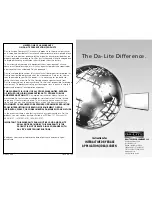
IDEA Screen
Brand: Da-Lite Pages: 2
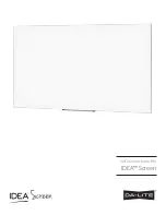
IDEA Screen
Brand: Da-Lite Pages: 8

Magnavox 60P 8241
Brand: Magnavox Pages: 54

51MP6100D - 51" Widescreen Hd Ready Tv
Brand: Magnavox Pages: 38

DHD1052
Brand: Christie Pages: 158

CP-S370
Brand: Hitachi Pages: 40

ML750ST
Brand: Optoma Pages: 57

VPS-80DS
Brand: Sony Pages: 8

LMP-F230
Brand: Sony Pages: 2


