background image

1

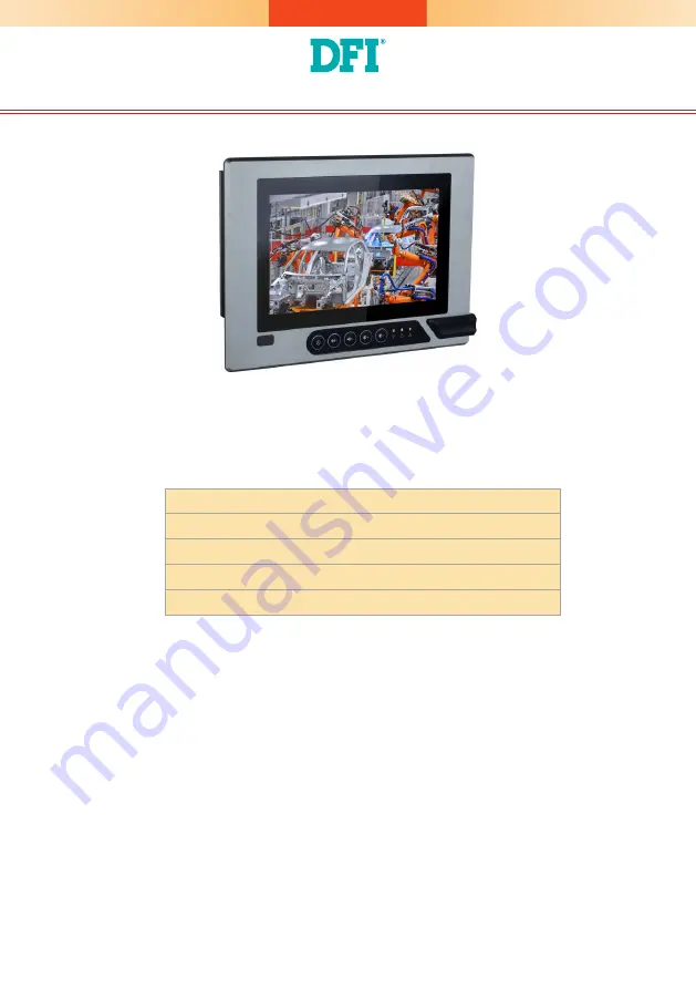
KS070/150/190/215-AL Installation Guide

Package Contents

• One 7", 15", 19", or 21.5" Modular Touch Panel PC

• 3-pin and 2-pin Terminal Block Connectors

• SATA and Mini PCIe Installation Screws

• 1 DVD disk includes:

   - Manual

DFI reserves the right to change the specifications at any time prior to the 

product's release. For the latest revision and more details of the installation 

procedure, please refer to the user's manual on the website.

www.dfi.com

Summary of Contents for KS070-AL

Page 1: ... Terminal Block Connectors SATA and Mini PCIe Installation Screws 1 DVD disk includes Manual DFI reserves the right to change the specifications at any time prior to the product s release For the latest revision and more details of the installation procedure please refer to the user s manual on the website www dfi com ...

Page 2: ... is applied 2 ATX Mode The system powers on via the power button or the auto power on setting in the BIOS 3 IGN Mode The system powers on via the ignition control with settings of on off delay in the BIOS plus low voltage protection i e the system will not power on if the car battery s voltage is below 10 5 21V and 42V for 12V input 24V and 48V input respectively Note that for this mode to work pl...

Page 3: ...IM card into the slot Please place the card with the IC fac ing down and the angled corner facing toward the socket so that it will be in contact with the system board Note Make sure that the SIM card is inserted completely into the socket you should feel a force of the spring that locks the card in place To release the card push it inward to un lock it Side View SIM Card Slot Screw ...

Page 4: ...ve tray The SATA drive tray can be easily accessed without opening the system However the system does not support hot swapping hard drives turn off the system first 1 Locate the drive tray on the bottom panel and open it by releasing the thumbscrews SATA Drive Tray Thumbscrew Mounting Screw Installing a SATA Drive ...

Page 5: ...DD into the drive bay by aligning the HDD s data and power connectors with the system s SATA data and power connectors Then close the drive tray and secure the drive in place with the thumbscrews SATA Power Data Cable ...

Page 6: ... to it have been powered off 2 Disconnect all power cords and cables 3 The 4 mounting screws on the rear side of the system are used to se cure the cover to the chassis Remove these screws and put them in a safe place for later use 4 Lift the cover to open the system 5 The Mini PCIe and the SODIMM slots are readily accessible after remov ing the chassis cover Mounting Screw Mounting Screw SODIMM S...

Page 7: ...CIe slots one full size black and one half size white slots Here we will demonstrate the installation of a full size Mini PCIe card working in conjunction with a SIM card for 3G 4G connectivity 1 Grasp the Mini PCIe card by its edges and align the notch in the con nector of the PCIe card with the notch in the connector on the system board 2 Push the Mini PCIe card down and use the provided mountin...

Page 8: ...stall a memory module grasp the memory module by its edges and align the module s notch with the socket s notch then insert the memory into the socket at an angle and push it down until you feel a click Insert the Memory at an Angle SODIMM Module Installed into the Socket ...

Page 9: ...r of the box module Note If the orientation of the assembly is not correct the box module will not seat evenly on top of the panel module which results in some space in between them and indicates that the ADP connectors are not engaged When this is the case please turn the box module the other way around ADP Connector Cover Screw Alignment Post 2 Hold the box module with its ADP connector in line ...

Page 10: ...re that the box module seats on top of the panel module with the alignment post effortlessly sliping into the designated holes on the box module Press to install these two modules and secure the installation with 4 mouting screws ...

Page 11: ...nting Options Wall mount Wall Mount Bracket 1 Wall Mount Bracket 2 Wall Mount Bracket 1 Mounting Screw 1 Before starting any installation procedures attach the poron foam to the Panel PC Poron Foam The VESA mount specifications for this device is 75 x 75 mm Please use a compatible VESA mount kit that can sustain the weight and size of this device ...

Page 12: ...el PC to wall mount bracket 1 to attach the two brackets with the hooks Then tighten the thumb screw to secure the assembly in place Note that the following diagram is for illustration only and may not resemble the actual product Wall mount Bracket 2 Thumb Screw Hooks Mounting Screw Thumb Screw ...

Page 13: ...m 19 447mm x 380mm 21 5 526 2mm x 342 6mm and ensure that the Panel PC can be fitted into the panel properly 4 Insert the Panel PC from the outside surface of the panel into the mounting hole until it is properly fitted against the panel 5 Position the mounting clamps along the rear edges of the Panel PC and insert them into the slits around the Panel PC 1 Before starting any installation procedur...

Page 14: ...sing an electric screwdriver by pressing the white plastic cap onto the back of the panel Note that the following diagram is for illustration only and may not resemble the actual product Note The maximum thickness of your panel s mounting wall should be 10 mm for secure panel mount Cap Slit for Mounting the Clamp Mounting Clamp 132 20 210 50 5 ...

Page 15: ...V 2 5V 3 Ground 4 Ground DIO J7 1 DIO7 2 DIO6 3 DIO5 4 DIO4 5 DIO3 6 DIO2 7 DIO1 8 DIO0 COM 3 COM 4 RS232 1 DCD 2 RXD 3 TXD 4 DTR 5 GND 6 DSR 7 RTS 8 CTS 9 RI DIO Power J9 1 12V 2 GND 3 5VSB 4 5V USB 2 0 6 7 J5 1 VCC 2 VCC 3 Data0 4 Data1 5 Data0 6 Data1 7 Ground 8 Ground 9 Key 10 NC Clear CMOS Data SW2 Normal default SW2 2 Off Clear CMOS SW2 2 On Power on Mode Select SW4 Power on via Ignition SW4...

Page 16: ... Use the following procedure to enable this function 1 Press Delete to enter the BIOS menu when the system powers on 2 Go to Advanced IGN Configuration IGN Mode Low Voltage Protection Enables low voltage protection to protect your car battery default Enabled Power on Power off Delay Enables it to allow the system to power on or off after the specified number of seconds default Disabled ...

Page 17: ... the power on or power off process Notes 1 Please save your changes of the BIOS settings Exit Exit Saving Changes 2 The Status LED on the bottom panel will start blinking once the above settings take effect 3 Please refer to the next page for system on off process with in vehicle power management ...

Page 18: ...ystem boots System on Flowcharts for Ignition Power Control Yes System on Low Voltage Protection Enabled No Power off Signal ACC off Counts down System off delay time System off Battery 10 5 V 12V input or 21V 24V input or 42 V 48V input No Yes Disconnects standby power These flowcharts illustrate the startup and shutdown processes that the system goes through using ignition power control After 30...

Reviews: