background image

E-1

2016. 3

Printed in China

©

 DEVELOP GmbH

/

INSTALLATION MANUAL

A795-9625-00

Applied Machines: 

/

<Important>

Be sure to correctly follow the procedures in order as explained in this Installation Manual.
If you do not follow the procedure in order, the image trouble may occur.

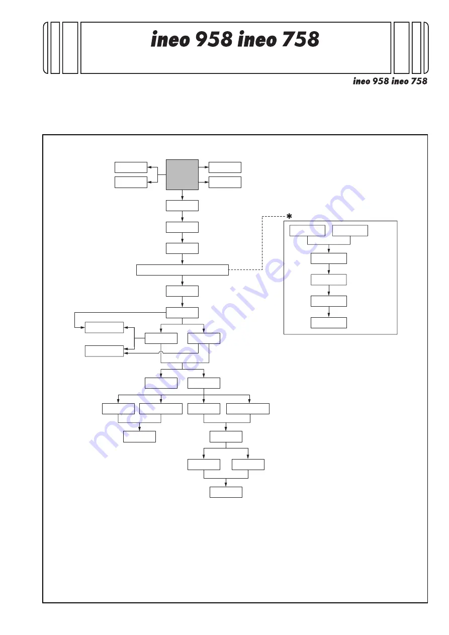
1. Outline of installation procedures

When installing the machine and associated options as a system, follow the order shown on the upper.

Caution:

    • When transporting the machine, assign an adequate number of persons to the job and follow the speci-

fied correct procedures.(mass: approx. 200 kg (440-15/16 lb))

Note:

    • For the detailed installation procedures for each option, follow the instructions given in the corresponding 

installation manual and perform the procedures correctly.

    • Once the Power Switch is turned ON, do not turn OFF it until the installation work has been completed.

AU-201S

AU-102

WT-506

MK-735

WT-513

SP-501

OT-508

RU-515

PK-520

MK-715

KP-101

KH-102

HT-508*

2

UK-501

LU-205

LU-303

FS-537

FS-536

FS-537SD

FS-536SD

FK-516*

1

UK-212*

1

SC-508*

1

HD-524*

1

EK-610*

1

EK-611*

1

Electronic system options

Electronic system options

Machine

JS-602

PI-507

PK-523

ZU-609

*1

:  No particular order in installation 

procedures

*2

:  Varies depending on the applicable 

marketing area

Summary of Contents for ineo 758

Page 1: ...d correct procedures mass approx 200 kg 440 15 16 lb Note For the detailed installation procedures for each option follow the instructions given in the corresponding installation manual and perform the procedures correctly Once the Power Switch is turned ON do not turn OFF it until the installation work has been completed AU 201S AU 102 WT 506 MK 735 WT 513 SP 501 OT 508 RU 515 PK 520 MK 715 KP 10...

Page 2: ...ce exposed to direct sunlight 6 Avoid a dusty location or a place near volatile and flammable substances 7 Avoid a poorly ventilated place 4 Notes on using touch panel Be sure to instruct users on the following points This machine uses a capacitive touch panel When you touch the touch panel use your fin ger or the stylus pen supplied with the machine If you touch the panel using your nail or a pen...

Page 3: ...Remove the stretch film from the machine No Name Q ty 1 User s guide holder 1 2 Quick start guide 1 3 Installation manual 1 set 4 User s guide CD 1 5 CD ROM 1 set 6 Tray label Paper size label 1 set 7 Panel sheet 1 8 Chart 1 9 Cap A black 2 10 Cap B white 1 11 Connector cover 1 12 Scanner cover 1 13 Mounting screw 3 x 8 mm 1 14 Spacer 1 15 Stylus pen 1 Keep this bag away from babies and children D...

Page 4: ...lastic bag 6 Position the slope as illustrated and drive nails in to fix the slope in position Caution Insert the nails in the outer holes 7 Holding onto the front cover and the back panel of the machine slide the machine down along the slope Caution Machine mass 200 kg 440 15 16 lb Perform this step on a level stable site and assign an adequate number of persons When sliding the machine down do n...

Page 5: ...e tape and protective mate rials Note Be sure to lock the lever after removing the protec tive tape A B 2 Remove the reinforcement plate Four screws 3 Remove the locking screws Note Keep the locking material It is necessary for trans porting the machine 4 Attach the supplied caps A and B A B ...

Page 6: ... tray 1 out and remove the protective tape from the tray Note See the User s Guide CD for instructions on set ting paper in each tray and configuring the paper types 8 Pull the tray 2 out and remove the protective tape from the tray 9 Pull trays 3 and 4 out and remove the desic cants 10 Remove the protective tape from trays 3 and 4 ...

Page 7: ...ox and close the lower front door 8 Installing the toner cartridge Note Since no toner cartridge is supplied with the machine purchase a toner cartridge separately 1 Shake the toner cartridge up and down five to ten times Note Shake the cartridge adequately Otherwise it may cause trouble 2 Remove protective tape of the toner cartridge 3 Open the upper front door and insert the toner cartridge into...

Page 8: ...er options To install other options refer to the installation man ual for each option and follow the Installation Proce dures 10 Mounting the accessory parts 1 Attach the supplied connector cover 2 Remove the protective cover from the supplied stylus pen Note Discard the removed protective cover 3 Set the stylus pen in the place shown in the illus tration ...

Page 9: ...ess Stop 3 on the control panel 3 Do not input date and time but touch Entry of the Date Time Setting 4 Input the time zone using up down keys or direct keys 5 Touch Entry of the Time Zone Setting 6 Touch Apply 7 Touch OK 8 Touch Next 14 Serial number input Note Serial number input is if necessary needed only for the optional devices installed in 9 Installing other options 1 Touch the item you wan...

Page 10: ...direction of installation or take measures to block the light source by covering it etc then perform installation checking again If a fluorescent light or other bright light sources exist right above the machine the light source can hinder installation checking and cause operation errors in the Non Image Area Erase Check For detailed information see the service manual 5 Touch OK 17 Changing paper ...

Page 11: ...nd of the hole until it stops Secure the plate with screws A5 POST Insert the paper guide plate rear into the hole and press it towards the front end of the hole until it stops Secure the plate with screws 5 Place a sheet of paper as large as the paper size you are setting in the bottom of the tray Align the paper guide plate front with the end of the sheet Gap between the sheet and the paper guid...

Page 12: ... detection Kit UK 501 Punch Kit PK 523 PK 520 Z Folding Unit ZU 609 Large Capacity Unit LU 205 LU 303 Fax Kit FK 516 Local Interface Kit EK 611 Security Kit SC 508 Authentication Unit AU 201S AU 102 Upgrade Kit UK 212 Hard Disk HD 524 Working Table WT 513 Network Fax 2 Exit from the Service Mode and return to the ini tial screen 19 Connecting the network cable 1 Connect the main body and networkin...

Page 13: ...h OK after the TCP IP Settings screen is displayed 5 Select the function to be used as follows Forward Forward Detail Settings PING Confirmation and make the operation check of TCP IP 21 Restarting the machine 1 Open the lower front door and turn OFF the power switch 2 Turn ON the power switch again after 10 or more seconds have passed then close the lower front door 22 Adjusting the height 1 Chec...

Page 14: ...r side will move up Counterclockwise The rear side will move down 23 Adjusting DF skew 1 Check how the edges of the chart are mis aligned The amount of the deviation of the first side of the chart will be X1 The amount of the deviation of the second side of the chart will be X2 2 Place the chart in the original tray with the first side facing up and the arrows directing to the left when viewed fro...

Page 15: ... the standard value perform the following adjustment Adjusting DF skew 1 side 1 Loosen the mounting screw on the right hinge viewed from the front 2 When the difference of the deviation is plus turn the adjustment screw located at the back of the reverse automatic document feeder clock wise to adjust Note Look at the guide lines when making the adjust ment When turning the screw be sure not to rai...

Page 16: ...ic document feeder until in an upright position To prevent the adjustment screw breakage be sure to follow the above instructions 4 After the adjustment is completed tighten the mounting screw on right side hinge securely with screwdriver Adjusting DF skew 2 side 1 Open the reverse automatic document feeder then remove the two screws shown in the illus tration 2 Close the reverse automatic documen...

Page 17: ...he width C between the chart and the copy sample is within the specified range Specifications 0 1 0 mm Back side magnification in the feeding direc tion Check whether the difference in the width D between the chart and the copy sample is within the specified range Specifications 0 1 0 mm Back side magnification in the main scanning direction Check whether the difference in the width E between the ...

Page 18: ...stable range 1 00 to 1 00 0 1 per step If the difference in the width E is greater than the specifications use the minus key If the difference in the width E is smaller than the specifications use the plus key 5 Touch Test Copy 6 Select the tray loading paper for the test copy 7 Touch 2 8 Touch 2 Sided 2 Sided 9 Place the chart in the original tray with the first side facing up and the arrows dire...

Page 19: ...width A is greater than the specifications enter a positive value If the difference in the width A is smaller than the specifications enter a negative value 5 Touch Test Copy 6 Select the tray loading paper for the test copy 7 Touch 2 8 Touch 2 Sided 2 Sided 9 Place the chart in the original tray with the first side facing up and the arrows directing to the left when viewed from the front 10 Press...

Page 20: ...hould be on the upper side and the paper size labels on the lower side 32 Installing the user s guide holder Install the user s guide holder 33 Installing the spacer Install the supplied spacer 34 Affixing the panel sheet Affix the supplied panel sheet to the surface of the operation panel Note The panel sheet is affixed on customer request The panel sheet must be kept by the customer ...

Page 21: ... Open the manual bypass tray and set the set guide for banner paper No Name Shape Q ty 1 Manual bypass tray 1 Keep this bag away from babies and children Do not use in cribs beds carriages or playpens The thin film may cling to nose and mouth and prevent breathing This bag is not a toy ...

Page 22: ... document feeder One screw each for right and left Change the set position of the stopper to the lower side and secure it in position Note Perform this step only when necessary No Name Shape Q ty 1 Stamp unit 1 2 Stamp 1 3 Installation manual 1 set Keep this bag away from babies and children Do not use in cribs beds carriages or playpens The thin film may cling to nose and mouth and prevent breath...

Page 23: ...der then remove the six screws 4 Close the reverse automatic document feeder 5 Remove the front cover 6 Open the top door 7 Remove the rear cover 8 Remove the screw then remove the pin Front at two places rear at one place 9 Open the original tray ...

Page 24: ...ote Tighten the unit together with the ground terminal 14 Connect the stamp unit connector to the main body relay connector 15 Store the relay connector at the position shown in the illustration and pass the stamp unit har ness through the gap of the rib Note Make sure that the harness does not interfere with the roller 16 To install the covers and other parts removed in steps 3 to 10 reverse the ...

Page 25: ...per to the upper side and secure it in position 3 Configuration procedures 1 Plug the power cord into the power outlet and turn ON the power switch 2 Display the Service Mode screen For details of how to display the Service Mode screen see the service manual 3 Touch System 2 4 Touch Stamp 5 Touch Set 6 Touch END 7 Touch Exit on the Service Mode screen ...

Reviews: