

DOP
-B10
High Color
‧
Wide Screen
‧
User-Friendly HMI Products
No.18, Xinglong Rd., Taoyuan City
33068, Taiwan
B10S615 / B10E615 Instrunction Sheet
(1) Preface
Thank you for purchasing DELTA’s DOP-B series. This instruction sheet will be helpful in the installation, wiring and inspection of
Delta HMI. Before using the product, please read this instruction sheet to ensure correct use. You should thoroughly understand all
safety precautions before proceeding with the installation, wiring and operation. Place this instruction sheet in a safe location for
future reference. Please observe the following precautions:
Install the product in a clean and dry location free from corrosive and inflammable gases or liquids.
Ensure that all wiring instructions and recommendations are followed.
Ensure that HMI is correctly connected to a ground. The grounding method must comply with the electrical standard of
the country (Please refer to NFPA 70: National Electrical Code, 2005 Ed.).
Do not disassemble HMI, modify or remove wiring when power is applied to HMI.
Do not touch the power supply during operation. Otherwise, it may cause electric shock.
If you have any questions during operation, please contact our local distributors or Delta sales representatives.
The content of this instruction sheet may be revised without prior notice. Please consult our distributors or download the most
updated version at
http://www.delta.com.tw/ia
(2) Safety Precautions
Carefully note and observe the following safety precautions when receiving, inspecting, installing, operating, maintaining and
troubleshooting. The following words, DANGER, WARNING and STOP are used to mark safety precautions when using the
Delta’s HMI product. Failure to observe these precautions may void the warranty!
Installation
Comply with quick start for installation. Otherwise it may cause equipment damage.
Do not install the product in a location that is outside the stated specification for the HMI. Failure to
observe this caution may result in electric shock, fire, or explosion.
Do not install the product in a location where temperatures will exceed specification for the HMI.
Failure to observe this caution may result in abnormal operation or damage the product.
Please note that this equipment has obtained EMC registration for commercial use. In the event
that it has been mistakenly sold or purchased, please exchange it for equipment certified for home
use.
Do not use this product as an alarm device for disaster early warning that may result in personal
injury, equipment damage, or system emergency stop.
Wiring
Connect the ground terminals to a class-3 ground (Ground resistance should not exceed 100
Ω
).
Improper grounding may result in communication error, electric shock or fire.
Operation
The users should use Delta Screen Editor software to perform editing in Delta's HMI product. To
perform editing and confirming HMI programs without using Delta Screen Editor software in Delta's
HMI product may result in abnormal operation.
To prevent the personal injury and equipment damage, when designing HMI programs, please
ensure that a communication error occurred between Delta’s HMI product and the connecting
controller or equipment will not result in system failure or malfunction.
Please be sure to backup the screen data and HMI programs in case they are lost, accidentally
deleted or worse.
Do not modify wiring during operation. Otherwise it may result in electric shock or personal injury.
Never use a hard or pointed object to hit or strike the screen as doing this may damage the screen
and let the screen has not respond at all, and then cause HMI to work abnormally.
Maintenance and Inspection
Do not touch any internal or exposed parts of the HMI as electrical shock may result.
Do not remove operation panel while power is on. Otherwise electrical shock may result.
Wait at least 10 minutes after power has been removed before touching any HMI terminals or
performing any wiring and/or inspection as an electrical charge may still remain in the HMI with
hazardous voltages even after power has been removed.
Turn the power off before changing backup battery and check system settings after finishing
change. (all data will be cleared after changing battery).
Be sure the ventilation holes are not obstructed during operation. Otherwise malfunction may result
due to bad ventilation or overheating troubles.
Wiring Method
Do not use a voltage that will exceed specification for the HMI. Failure to observe this caution may
result in electric shock or fire.
Remove the terminal block from the HMI before wiring.
Insert only one wire into one terminal on the terminal block.
If the wiring is in error, perform the wiring again with proper tools. Never use force to remove the
terminals or wires. Otherwise, it may result in malfunction or damage.
For the power line that forced to take out, ensure to check wiring again and restart.
Communication Wiring
Comply with communication wiring specification for wiring.
Wiring length should comply with the stated specification for the HMI.
Proper grounding to avoid bad communication quality.
To avoid noise and interference, the communication cable, all power cables, and motor power
cable should be placed in separate conduits.
(3) Pin Definition of Serial Communication
DOP-B10S615 / DOP-B10E615 COM1 Port (Supports Flow Control)
COM Port
PIN
Contact
RS-232
1
2
RXD
3 TXD
4
5 GND
6
7 RTS
8
CTS
9
Note: Blank = No Connection.
DOP-B10S615 / DOP-B10E615 COM2 Port (Supports Flow Control)
COM Port
PIN
MODE1
MODE2
MODE3
RS-232
RS-422
RS-485
1 TXD+ D+
2
RXD
3 TXD
4
RXD+
5 GND GND GND
6
TXD-
D-
7 RTS
8
CTS
9 RXD-
Note1: Blank = No Connection.
Note2: When COM2 port is used for RS-232 flow control, i.e. RTS and CTS signals are used for flow control, COM3 port will become
incapable of being used.
Note3: When COM2 port is used for RS-422 flow control, please refer to the following COM3 Port signals table for pin assignments. The
signals, RTS+, CTS+, RTS- and CTS- shown in brackets are the signals used for flow control.
DOP-B10S615 / DOP-B10E615 COM3 Port
COM Port
PIN
MODE1
MODE2
MODE3
RS-232
RS-422
RS-485
1
TXD+(RTS+)
D+
2
RXD
3 TXD
4
RXD+(CTS+)
5 GND GND GND
6
TXD-(RTS-)
D-
7
8
9
RXD-(CTS-)
Note1: Blank = No Connection.
Note2: When COM2 port is used for RS-422 flow control, please refer to the COM3 Port signals table above for pin assignments. The signals,
RTS+, CTS+, RTS- and CTS- shown in brackets are the signals used for flow control.
DOP-B10E615 Ethernet Interface (LAN)
Ethernet Interface (LAN)
PIN
Contact
Ethernet
1 TX+
2
TX-
3 RX+
4
5
6
RX-
7
8
Note: Blank = No Connection.
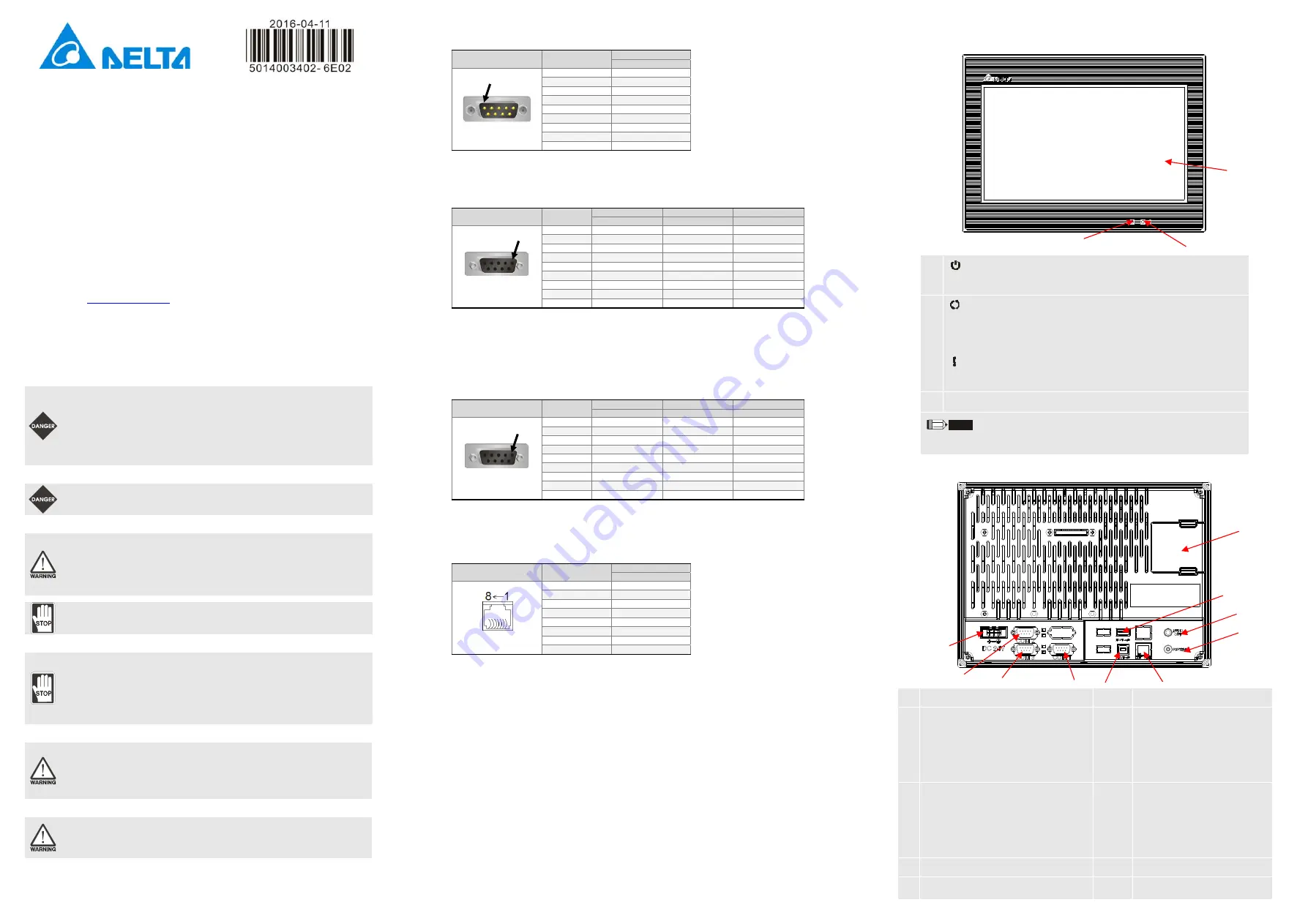
(4) Parts Names
DOP-B10S615
/
DOP-B10E615 (Front View)
A
: Power LED Indicator
Lights in green when HMI works normally.
B
: Operation LED Indicator (Blue)
(Note1)
The operation LED indicator blinks in blue when either the communication is carried out or the
data is accessing (please refer to the “Note1” below for explanation).
: Alarm LED Indicator (Red)
The alarm LED indicator blinks in red when one of the alarms is on.
C
Touch Screen / Display
NOTE
1. The definition of the operation LED indicator (Blue) can be determined by the users freely.
DOP-B10S615
/
DOP-B10E615 (Rear View)
A
Power Input Terminal
F
Ethernet Interface (LAN)
B
COM2
(It is provided with two LED indicators to indicate
that HMI is in Read or Write status during the
communication process.)
G
Memory Card Slot / Battery Cover
C
COM3
(It is provided with two LED indicators to indicate
that HMI is in Read or Write status during the
communication process.)
H
USB Host
D
COM1
I
Audio Output Interface
E
USB Slave
J
System Key
PIN1
PIN1
PIN1
C
B
A
H
E
F
I
A
B
C
D
J
G


