


w w w . d e l l . c o m | s u p p o r t . d e l l . c o m
Dell™ Dimension™ E521
Owner’s Manual
Model DCSM
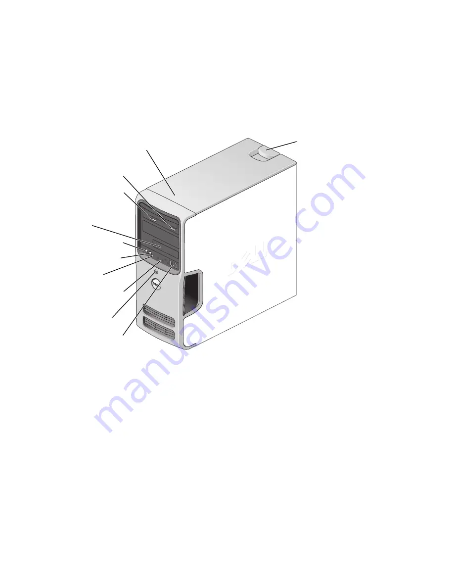
FlexBay for optional
floppy drive or Media
Card Reader
hard-drive activity light
microphone connector
headphone connector
CD or DVD activity light
CD or DVD eject button
diagnostic lights
USB 2.0 connectors (2)
cover latch
release
Service Tag
power button/
power activity light
Summary of Contents for E521 - Dimension Motherboard UW457 0UW457
Page 8: ...8 Contents ...
Page 12: ...12 Finding Information ...
Page 64: ...64 Troubleshooting Tools ...
Page 164: ...64 Index 164 Index ...


