


w w w . d e l l . c o m | s u p p o r t . d e l l . c o m
Dell™ Dimension™ E521
Owner’s Manual
Model DCSM
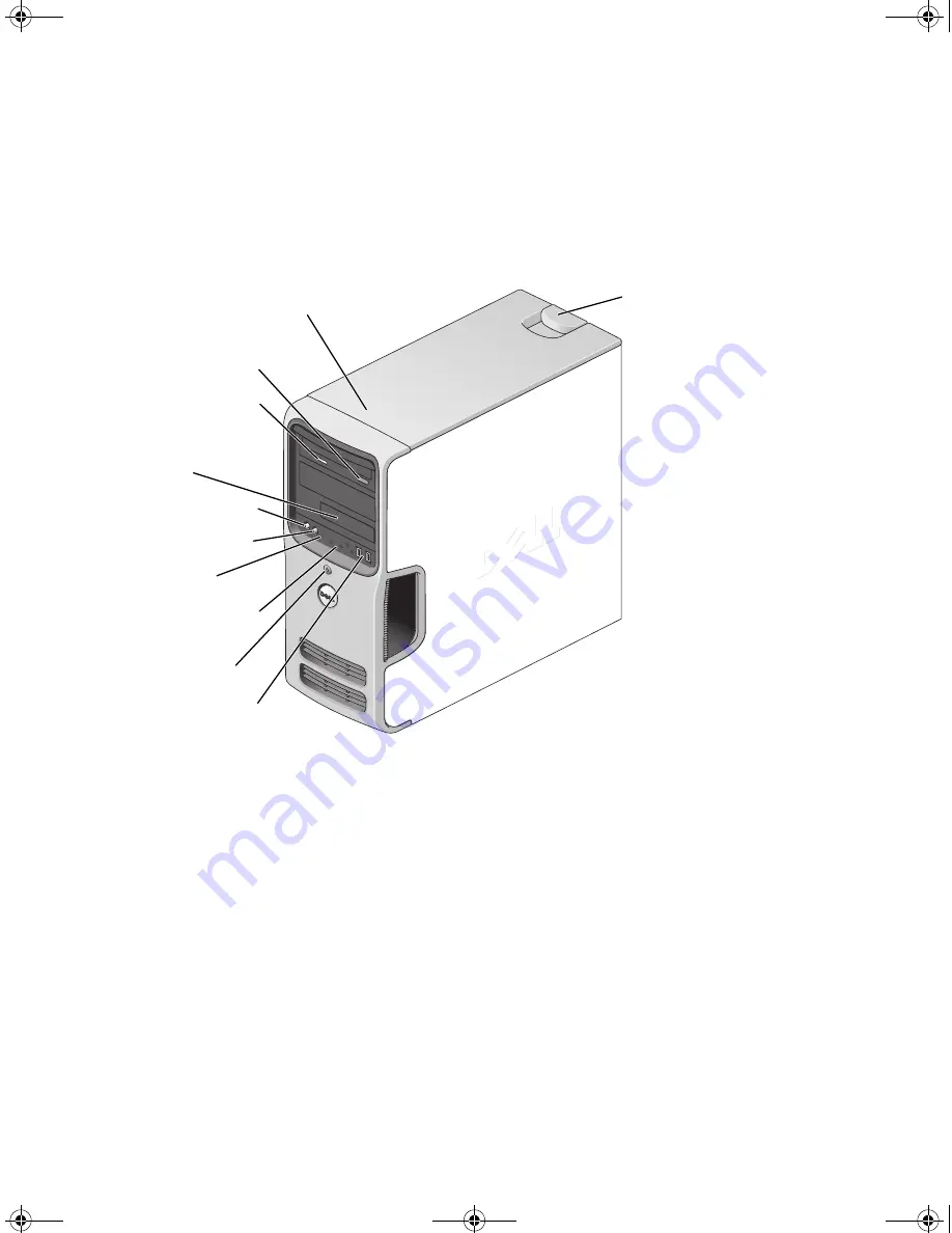
FlexBay for optional
floppy drive or Media
Card Reader
hard-drive activity light
microphone connector
headphone connector
CD or DVD activity light
CD or DVD eject button
diagnostic lights
USB 2.0 connectors (2)
cover latch
release
Service Tag
power button/
power activity light
book.book Page 1 Monday, July 23, 2007 3:47 PM
Summary of Contents for Dimension PY349
Page 8: ...8 Contents book book Page 8 Monday July 23 2007 3 47 PM ...
Page 32: ...32 Setting Up and Using Your Computer book book Page 32 Monday July 23 2007 3 47 PM ...
Page 60: ...60 Troubleshooting Tools book book Page 60 Monday July 23 2007 3 47 PM ...
Page 106: ...106 Removing and Installing Parts book book Page 106 Monday July 23 2007 3 47 PM ...


