Dataradio Gemini/PD+, Installation Manual
The Dataradio Gemini/PD+ is an advanced communication solution, ensuring reliable data transmission. Enhance your device's functionality by downloading the free Installation Manual. Get the most out of your Gemini/PD+ by accessing the detailed manual directly from manualshive.com. Essential for optimal setup and operation.
Share
Download


Reviews:
No comments
Related manuals for Gemini/PD+

NB100
Brand: NetComm Pages: 1

1088/I
Brand: Patton electronics Pages: 13

M5250
Brand: TP-Link Pages: 69

DWA-123
Brand: D-Link Pages: 42
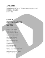
DSL-3782
Brand: D-Link Pages: 64

DSL-300G+
Brand: D-Link Pages: 42

DWA-X3000
Brand: D-Link Pages: 19

DSL-322T
Brand: D-Link Pages: 66

DWA-X3000
Brand: D-Link Pages: 2
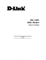
DSL-302G
Brand: D-Link Pages: 99
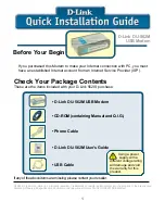
DU-562M
Brand: D-Link Pages: 84
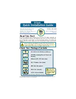
DSL-302G
Brand: D-Link Pages: 12

DSL-4320L
Brand: D-Link Pages: 154

DSL-300T
Brand: D-Link Pages: 57

DSL-320B
Brand: D-Link Pages: 63

DSL-302T
Brand: D-Link Pages: 69

DSL-380T
Brand: D-Link Pages: 66
DU-562M
Brand: D-Link Pages: 31


