


Smart-VS
QUICK REFERENCE GUIDE
Download the Smart-VS Product
Reference Guide by reading
the QR code here or see the
paragraph below.
SUPPORT THROUGH THE WEBSITE
Datalogic provides several services as well as technical
support through its website.
.
For quick access, from the home page click on the
search icon, and type in the name of the product you’re
looking for. This allows you access to download Data
Sheets, Manuals, Software & Utilities, and Drawings.
Hover over the Support & Service menu for access to
Services and Technical Support.
INSTALLATION PROCEDURE
1. Physically mount the Smart-VS device.
2. Make the necessary electrical connections.
3.
Configure the device using the embedded HMI or
the Smart-VS WebApp by connecting to the device
via Ethernet. The WebApp is accessible opening an
Internet browser (Google Chrome is recommended)
and entering the device IP address 192.168.3.100
in the address bar.
HMI INTERFACE
NO GOOD object
•
in Teach phase: blinking, NO GOOD object
teaching
•
in Run phase: NO GOOD object detected
• for future use
Trigger
• in Teach phase: trigger input status
• in Run phase: trigger received
GOOD object
•
in Teach phase: blinking, GOOD object
teaching
•
in Run phase: GOOD object detected
Run
• steady: device in Run phase
• blinking: Teaching required
BUTTON TEACHING PROCEDURE
The Run LED will blink until the Teaching procedure is
entered (e.g. device factory default).
Long press (> 4s, until the red LED on HMI lights up)
the HMI Button to enter the Teaching procedure.
1.
GOOD objects required to be
taught (green LED and green
spot blink).
2.
Place the GOOD object in
front of the Aiming System.
3. Place the trigger sensor
properly. The Trigger LED
indicates object detection.
4. Short press (< 1s) the HMI
Button to acquire the image.
More than one GOOD
object can be acquired. It
is suggested to acquire one
image per GOOD object
instance. Camera parameters
are auto-adjusted on the first
acquisition only.
5.
Long press (
> 4s, until the red
LED on HMI lights up
) the
HMI Button to start acquiring
NO GOOD objects. Red LED
and red spot start blinking.
6. Place the NO GOOD object
in front of the Aiming System.
Check the Trigger LED.
7.
Short press (< 1s) the HMI
Button to acquire the image.
More than one NO GOOD
object can be acquired.
8. Long press (
> 4s, until the
red LED on HMI lights up
)
the HMI Button to enter the
automatic learning procedure
(LEDs game). At the end,
the device will enter the Run
Phase.
The Teaching procedure can also be
entered when in Run phase: press the
HMI Button for 2s (yellow LED on HMI) for
incremental teaching or 4s (red LED on
HMI) to cancel and re-teach. Refer to the
Product Reference Guide for more details.
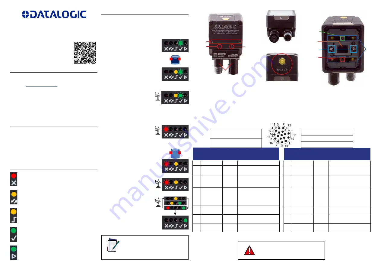
NOTE
1
2
3
4
6
7
5
11
8
9
10
1.
Bracket Mounting Holes (2)
2. Power On LED
3. Ethernet Connection LED
4. 90° Rotating Connector Block
5.
HMI Interface
6.
Ethernet Connector
7.
Power - I/O Connector
8.
Lens
9.
LED Aiming System
10. Red Spot (NO GOOD)
11.
Green Spot (GOOD)
12.
White Polarized Illuminators
M12 17-pin Power, and I/O Connector Pinout
(9 stripped wires)
Pin
Color
Name Function
1
2
Brown
Blue
Vdc
GND
PWR supply input v
PWR supply input voltage -
Connector
case
Chassis Connector case provides
electrical connection to
chassis
6
5
13
3
Yellow
Pink
Green
White
I1A *
I1B *
I2A *
I2B *
Trigger Input A
Trigger Input B
Remote Teach A
Remote Teach B
9
Red
O1 **
Data Valid (default is Push-
Pull)
8
Gray
O2 **
GOOD Output (default is
Push-Pull)
16
Black
O3 **
NO-GOOD Output (default
is Push-Pull)
*
Polarity insensitive
**
Short-circuit protected and
software programmable
12
For proper installation, it is recommended
to trim out all unused wires.
WARNING
M12 17-pin Power, and I/O Connector Pinout
(17 stripped wires)
Pin
Color
Name Function
1
2
Brown
Blue
Vdc
GND
PWR supply input v
PWR supply input voltage -
Connector
case
Chassis Connector case provides
electrical connection to
chassis
6
5
13
3
Yellow
Pink
White/Green
White
I1A *
I1B *
I2A *
I2B *
Trigger Input A
Trigger Input B
Remote Teach A
Remote Teach B
9
Red
O1 **
Data Valid (default is Push-
Pull)
8
Gray
O2 **
GOOD Output (default is
Push-Pull)
16
Yellow/Brown
O3 **
NO-GOOD Output (default
is Push-Pull)
CAB-GD03 M12-17P 3M power and
I/O cable, isolated wires (95A900052)
CAB-GD05 M12-17P 5M power and
I/O cable, isolated wires (95A900053)
CAB-GD03 M12 F/L 3M Free wires
CAB-GD05 M12 F/L 5M Free wires
CAB-GD10 M12 F/L 10M Free wires


