background image


DS2X00N-DS4800 SCANNER FAMILY 

SETUP PROCEDURE USING PROGRAMMING BARCODES 


1 ID-NET™ NETWORK SETUP USING PROGRAMMING 

BARCODES 


For any DS2x00N-DS4800 Family scanner, programming barcodes can be used to setup the 
ID-NET™ built-in high-speed interface dedicated for high-speed reader interconnection. 
ID-NET™ is in addition to the Main and Auxiliary serial interfaces. 
 
Following topologies are available: 


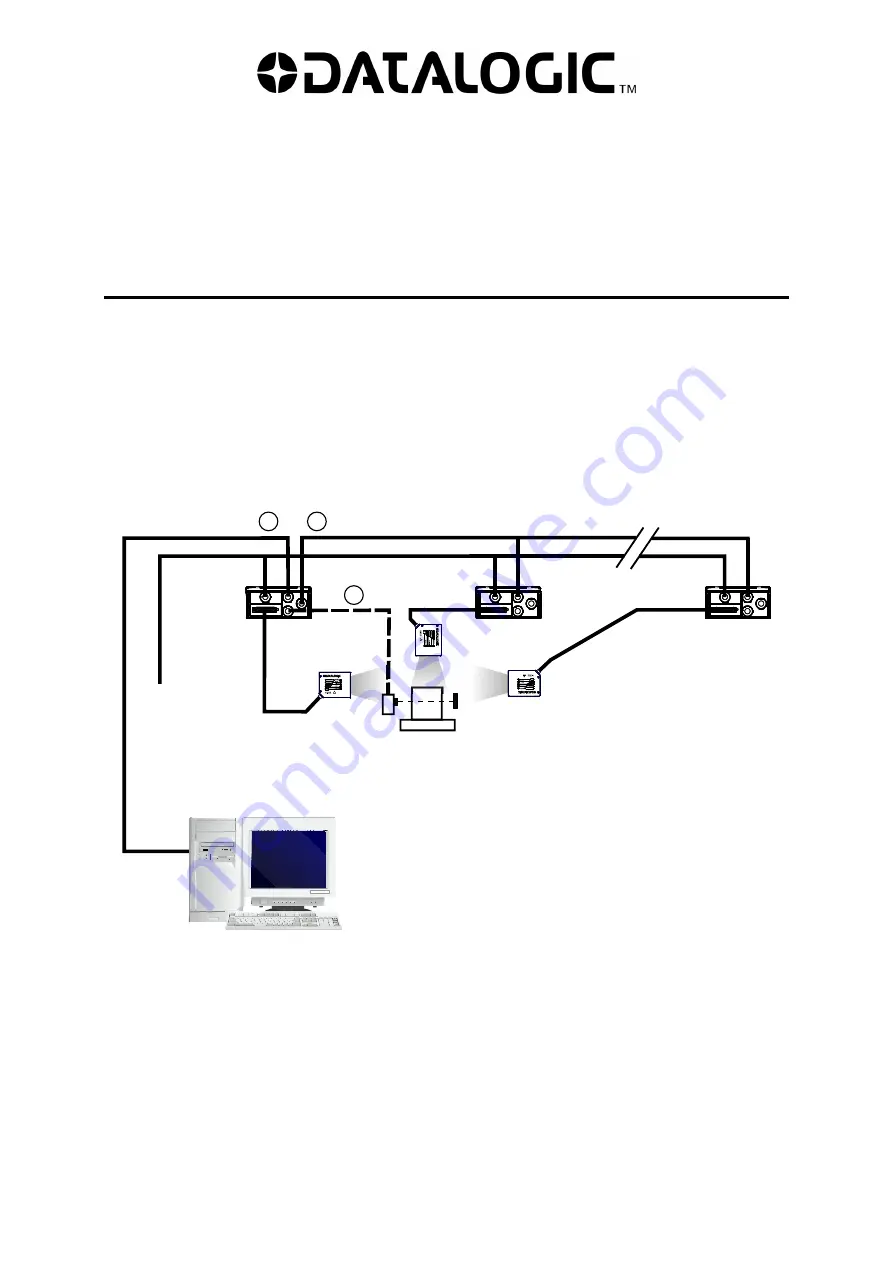
ID-NET™ M/S Synchronized

: Single station – multiple scanners 


The ID-NET™ interface allows local connection of multiple scanners that are reading on 
different sides of the same target. All scanners share a single presence sensor and 
activate/deactivate simultaneously. 
 
At the end of each reading phase a single data message is transmitted to the host. 
 
Thanks to ID-NET™, data communication among scanners is highly efficient so that an 
immediate result will be available. 


Main Serial Interface (RS232 or RS485) 

 External Trigger (for On-Line Mode) 

 ID-NET™ (up to 16 devices - practical limit) 

Host 

1

Master 

Slave#1

Slave#n 

Power 

Summary of Contents for DS2x00N-DS4800 Series

Page 1: ... S Synchronized Single station multiple scanners The ID NET interface allows local connection of multiple scanners that are reading on different sides of the same target All scanners share a single presence sensor and activate deactivate simultaneously At the end of each reading phase a single data message is transmitted to the host Thanks to ID NET data communication among scanners is highly effi...

Page 2: ... the end of each reading phase every scanner transmits its own data message to the host Thanks to ID NET data collection among readers is accomplished at a high speed without the need of an external multiplexing device This leads to an overall cost reduction and to simplified system wiring Terminal Main Serial Interface RS232 or RS485 Auxiliary Serial Interface Local Echo RS232 External Trigger fo...

Page 3: ... 4 seconds Release the button to enter the AutoLearn Mode The laser beam turns ON and the yellow LEARN LED blinks the AutoLearn Mode is working 2 Now put the barcode related to the planned role and address in front of the scanner The picture below shows as example the scanner configuration as Slave 1 1 3 Once the scanner has successfully read the code the LEDs stay on steady for 2 seconds SETUP LE...

Page 4: ...eady LED is on SETUP LEARN TEST READY GOOD TRIGGER COM STATUS Programming done 5 Repeat steps 1 3 above to configure all the slaves and master The maximum number of scanners is 32 including the master 6 Connect the master scanner to a PC by means of the Genius configuration software Master Master Slave 1 Slave n ...

Page 5: ...ming Barcodes 5 7 Start the Genius Express Network Setup procedure Refer to the Help On Line document for details NOTE Any network role can also be programmed using Genius Refer to the Help On Line documentation for further details ...

Page 6: ...g Programming Barcodes 6 NETWORK LAYOUT BARCODES ID NET M S Synchronized Ì SYN00 dÎ Master Ì SYN01 kÎ Slave 1 Ì SYN02 rÎ Slave 2 Ì SYN03 yÎ Slave 3 Ì SYN04 ÄÎ Slave 4 Ì SYN05 ÂÎ Slave 5 Ì SYN06 Î Slave 6 Ì SYN07 Î Slave 7 ...

Page 7: ...dure Using Programming Barcodes 7 ID NET M S Synchronized Ì SYN08 5Î Slave 8 Ì SYN09 Î Slave 9 Ì SYN10 jÎ Slave 10 Ì SYN11 qÎ Slave 11 Ì SYN12 xÎ Slave 12 Ì SYN13 ÃÎ Slave 13 Ì SYN14 ÊÎ Slave 14 Ì SYN15 Î Slave 15 ...

Page 8: ...Procedure Using Programming Barcodes 8 ID NET M S Multidata Ì MUL00 8Î Master Ì MUL01 Î Slave 1 Ì MUL02 FÎ Slave 2 Ì MUL03 MÎ Slave 3 Ì MUL04 TÎ Slave 4 Ì MUL05 Î Slave 5 Ì MUL06 bÎ Slave 6 Ì MUL07 iÎ Slave 7 ...

Page 9: ...edure Using Programming Barcodes 9 ID NET M S Multidata Ì MUL08 pÎ Slave 8 Ì MUL09 wÎ Slave 9 Ì MUL10 Î Slave 10 Ì MUL11 EÎ Slave 11 Ì MUL12 LÎ Slave 12 Ì MUL13 SÎ Slave 13 Ì MUL14 ZÎ Slave 14 Ì MUL15 aÎ Slave 15 ...

Page 10: ...ure Using Programming Barcodes 10 ID NET M S Multidata Ì MUL16 hÎ Slave 16 Ì MUL17 oÎ Slave 17 Ì MUL18 vÎ Slave 18 Ì MUL19 Î Slave 19 Ì MUL20 DÎ Slave 20 Ì MUL21 KÎ Slave 21 Ì MUL22 RÎ Slave 22 Ì MUL23 YÎ Slave 23 ...

Page 11: ...dure Using Programming Barcodes 11 ID NET M S Multidata Ì MUL24 Î Slave 24 Ì MUL25 gÎ Slave 25 Ì MUL26 nÎ Slave 26 Ì MUL27 uÎ Slave 27 Ì MUL28 Î Slave 28 Ì MUL29 ÇÎ Slave 29 Ì MUL30 JÎ Slave 30 Ì MUL31 QÎ Slave 31 ...

Page 12: ...The programming barcode procedure uses the AutoLearn Mode as described in chapter 1 Ì OTHA rÎ Stand Alone NOTE The Stand Alone configuration can also be programmed using Genius Refer to the Help On Line documentation for further details Terminal Scanner 1 2 3 Main Serial Interface RS232 or RS485 Full Duplex Auxiliary Serial Interface Local Echo RS232 External Trigger for On Line Mode Host PG6000 C...

Page 13: ...ribed in chapter 1 The code below is a toggle code if the key is locked the programming code will unlock the key if the key is unlocked the programming code will lock the key Ì KLOCK Î Lock Unlock X PRESS key 4 RESTORE DEFAULT PARAMETERS BARCODE The programming barcode procedure uses the AutoLearn Mode as described in chapter 1 The code below allows setting the scanner to its factory default value...

Page 14: ...ocedure uses the AutoLearn Mode as described in chapter 1 The code below is a toggle code if the Network Status Monitor is disabled the programming code enables it if the Network Status Monitor is enabled the programming code disables it Ì NETDISP GÎ Network Status Monitor Network Status Monitor On the Master display the following messages are shown 1 N e t w o r k 1 5 1 6 N e t w o r k 3 1 Where ...

Page 15: ...sing Ethernet TCP IP For scanner configuration through Genius using Ethernet TCP IP follow one of the procedures in the next paragraph Ì CBETHN Î Ethernet TCP IP enabled DHCP disabled uses static IP Address parameters The Factory Default static IP address parameter settings for all DS2x00N DS4800 Family scanners are IP Address 172 16 11 0 Subnet Mask 255 255 0 0 Gateway Address 172 16 0 2 IP ADDRE...

Page 16: ... different IP addresses at each powerup therefore steps 2 4 of the above procedure may need to be repeated at successive connections between Genius and the scanner Static IP Addressing DHCP Disabled 1 Read the Ethernet TCP IP enabled DHCP disabled barcode using the X PRESS Autolearn function as described in chapter 1 2 Before changing the Ethernet network settings on the PC running Genius close an...

Page 17: ...ields as follows and click OK to save 6 Set the Genius Tools Options Communications window to TCP IP and in the Device address or name field input the scanner Factory Default address The port number is 51235 Then click OK 7 Perform a Device Get configuration from Genius ...

Page 18: ...ut with QL500 TCP IP Ethernet Interface to Host The Master reader must be configured for Ethernet communication using the specific programming barcode Host QL500 PS Power CAB PW EXT DS2100N Ethernet Host QL200 PS Power Ethernet Interface CBL 1490 ID NET Terminator The ID NET network must be terminated inserting an ID NET terminator into the last QL in the network ID NET on the QL500 is internally ...

Page 19: ...rface to Host BM200 210 TCP IP Ethernet Interface External Trigger ID NET up to 16 devices practical limit Host 1 3 2 Master Slave 1 Slave n Power CBX500 Terminal BM200 210 TCP IP Ethernet Interface Auxiliary Serial Interface Local Echo RS232 External Trigger for One Shot or Phase Mode ID NET up to 32 devices max network extension of 1000 m Host 1 3 2 Master Slave 1 Slave n Power CBX500 4 ...

Page 20: ...de Operating Mode Selection On Line Slave Synchronized Topology Role Slave Synchronized Slave Address xx Operating Mode Operating Mode Selection On Line Master Multidata Topology Role Master Multidata Slave Multidata Topology Role Slave Multidata Slave Address xx Ethernet TCP IP DHCP Enabled CBX Gateway Host Interface Type Ethernet TCP IP IP Addressing DHCP Ethernet TCP IP DHCP Disabled CBX Gatewa...

Reviews: