DAN DRYER 3000-3002-3006, User Manual
Introducing the DAN DRYER 3000-3002-3006: a powerful and efficient device that encompasses user-friendliness and reliability. Unlock the full potential of this product with a comprehensive User Manual available for free download from manualshive.com. Get the most out of your DAN DRYER experience by accessing this detailed manual today.
Share
Download


Reviews:
No comments
Related manuals for 3000-3002-3006
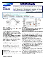
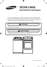
WF520ABP/XAA
Brand: Samsung Pages: 7
DV5471AEP/XAC
Brand: Samsung Pages: 12

EASY FRY
Brand: T-Fal Pages: 17

AdoraDry V6000
Brand: V-ZUG Pages: 40

LDEA400AC
Brand: Admiral Pages: 4

0141000
Brand: SEVERIN Pages: 64

FR-18
Brand: Saivod Pages: 44

FA-5053-5
Brand: TZS First AUSTRIA Pages: 32

TDHP 871
Brand: Hotpoint Pages: 20

HD3033
Brand: Philips Pages: 39

HD6156
Brand: Philips Pages: 52

Cucina HD6141
Brand: Philips Pages: 80

Cucina HD6150
Brand: Philips Pages: 92

HD6105
Brand: Philips Pages: 134

HD6146
Brand: Philips Pages: 144

Cucina HD6152
Brand: Philips Pages: 134

Cucina HD6140
Brand: Philips Pages: 168

SCI 0016 CI
Brand: FAR Pages: 32


