background image

(WSA10)

Daintree

®


Sensor Adapter

BEFORE YOU BEGIN 

Read these instructions completely and carefully.

Save these instructions for future use.

1

Installation Process

Installation Guide 

WSA10 |  DT104

Risk of electrical shock. Disconnect power before servicing or  

installing product. 

Install in accordance with National Electric Code and local codes.

WARNING

Risk of injury. Wear safety glasses and gloves during installation and 

servicing.

CAUTION

The Daintree Networks 

WSA10 Wireless Sensor Adapter

 is a 

control component within the Daintree Networked platform. 

The WSA10 enables open, standards based ZigBee wireless 

control communications with a variety of sensor devices used 

in HVAC systems.
The WSA10 provides up to four (4) thermistor temperature sensor 

inputs for temperature monitoring and logging, and up to two (2) 

0-10V analog inputs suitable for connection to a broad range of 

transducers, enabling wireless control and management of wired 

end-devices within the Daintree Networked platform.

Error/Test 

— On when the Wireless Adapter is in an error state. 

Flashes to indicate unit Reset and during Installation Test Mode (red).

Joined 

— On when the Wireless Adapter has joined a ZigBee

®

 network. 

Flashes to indicate Reset and during sensor Installation Test Mode (green).

Power 

— On when power is applied to the Wireless Adapter (green). 


LED Indicators

1. Disconnect power to the 24V power supply before 

 installation. 

Confirm that power is off before continuing.

2.


IMPORTANT: Use the provided Plan label to identify the  


  wireless-adapted sensor location on the building’s floorplan.

3.

 Mount the WSA10 on a flat surface in the HVAC packaged unit,  

  or in the facility’s electrical/mechanical room. See 

Mounting

.

4.

 Connect low voltage wiring between the WSA10 and the 

  power  supply and sensors as appropriate. Connect the sensor

  cable shield drain wire as appropriate. Improper connection 

  of the shield drain may cause incorrect or unstable sensor 

  readings. See 

Wiring

.

5. 

Check wiring then restore power to the power supply.

6.

 Ensure the WSA10 green Power        LED is On.

7.

 Press and hold the Reset button on the WSA10 for 3 seconds 

  to reset the unit. Release the button when the green Joined       

         LED and the red Error        LEDs begin flashing.

IMPORTANT: Reset the WSA10 as described above after adding 

sensors or making any change towiring connections.

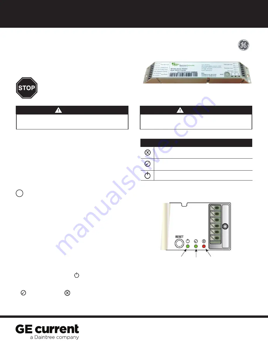
Figure 1: LED indicators

Power

LED

Joined

LED

Error

LED

Summary of Contents for GE Current WSA10

Page 1: ...t and during Installation Test Mode red Joined On when the Wireless Adapter has joined a ZigBee network Flashes to indicate Reset and during sensor Installation Test Mode green Power On when power is applied to the Wireless Adapter green LED Indicators 1 Disconnect power to the 24V power supply before installation Confirm that power is off before continuing 2 IMPORTANT Use the provided Plan label ...

Page 2: ...ctions 0 10V sensors and NTC thermistors using a DC Power Supply Figure 3 WSA10 terminal connections for 0 10V sensors and NTC thermistors using a WFA100 SN for DC Power Supply NOTE WFA100 SN is inside an approved electrical fixture or enclosure to provide double insulation of the line voltage wiring ...

Page 3: ...or and NTC thermistors using a WGA100 or WA100 family adaptor for DC Power Supply Figure 5 WSA10 terminal connections for 0 10V sensors and NTC thermistors using an AC Power Supply adaptor for DC Power Supply To reduce AC noise on the sensor signal line install the AC to DC power supply near the WSA10 rather than near the sensor s ...

Page 4: ...h terminal can accept one conductor only Connect only one 24AWG to 16AWG wire to any terminal All installation and maintenance of line voltage equipment must be performed by a qualified electrician The WSA10 must be installed in accordance with all local state and national electrical codes and requirements If the sensor cable includes a shield terminate the end closest to the WSA10 as shown in the...

Page 5: ...SA10 or you can write the last 4 or 5 digits on the floor plan This information will be used during the commissioning process After the system installation is complete a marked up copy of the facility floor plan showing the identity and location of each wireless adapter including associated sensors should be available This will simplify and expedite the commissioning process After the WSA10 is pow...

Page 6: ...tside of the designated range 7 Reports The Zone Temperature Analysis report displays temperature and time as reported by a temperature sensor or thermostat It also displays a histogram representing the time spent at various temperatures over the report time period When a time is selected on the histogram the number of hours spent above or below the selected temperature also displays An input s De...

Page 7: ...temp Backup operation only Inputs Resistance 4 Thermistor 10K Type 2 Accuracy 0 5 C 10 C to 45 C 14 F to 113 F 1 C 30 C to 65 C 22 F to 149 F Voltage 2 0 10VDC Accuracy 2 of span without calibration Radio Properties 2 4 GHz 8 dBm Range dependent on RF propagation variables Operating Relative humidity 5 to 95 Environment non condensing Temperature 32 to 122 F 0 to 50 C Compliance US FCC Part 15 Can...

Reviews: