Cyber Power CR U6 Series, User Manual
The Cyber Power CR U6 Series offers top-notch power protection for your electronic devices. With its advanced features and reliable performance, it is essential to have a comprehensive User Manual. Download your free manual from manualshive.com and unlock the full potential of your Cyber Power CR U6 Series to safeguard your equipment effectively.
Share
Download


Reviews:
No comments
Related manuals for CR U6 Series

CUBE-iT
Brand: Chatsworth Products Pages: 4

Cabinet H9A11
Brand: Compaq Pages: 32

MP004561
Brand: multicomp pro Pages: 2

824JXD
Brand: JetStor Pages: 49

R4-G002S
Brand: Red4Power Pages: 28

GAMING CALLEO WHITE
Brand: 2E Pages: 31

GAI-TRONICS 703-002
Brand: Hubbell Pages: 9
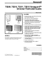
Versaguard TG509
Brand: Honeywell Pages: 12

HPB407
Brand: Honeywell Pages: 2

Fire-lite ROME Series
Brand: Honeywell Pages: 6

Backup4all
Brand: Edge Pages: 40

AWO 220PU
Brand: Pulsar Pages: 4

AWO 256PU
Brand: Pulsar Pages: 4

AE-235
Brand: Vivotek Pages: 6

DataPort 3
Brand: CRU Dataport Pages: 2

17A00
Brand: Leviton Pages: 21

ENC 10/12
Brand: Campbell Pages: 51

PANZONE PZBASE3
Brand: Panduit Pages: 6


