background image

Installation  and  Programming  Instructions  for  Electronic  Stand-Alone  Cylindrical  Locks

Installation  and  Programming  Instructions

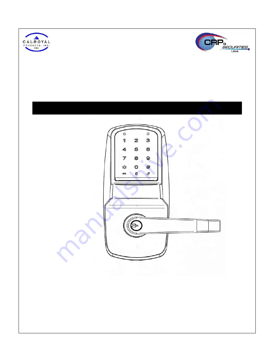
Stand-alone Touchscreen Access Lock

ANSI/BHMA Grade1

Take the time to read through this guide to familiarize yourself with the features and operation 
of  the lock, and its quick and easy programming procedures.

Save this PROGRAMMING INSTRUCTIONS for future reference. 

■   

Note

: Improper installations may result in damage to the lock and void the factory warranty.

Summary of Contents for CAL-ROYAL Grade1

Page 1: ...Touchscreen Access Lock ANSI BHMA Grade1 Take the time to read through this guide to familiarize yourself with the features and operation of the lock and its quick and easy programming procedures Save this PROGRAMMING INSTRUCTIONS for future reference Note Improper installations may result in damage to the lock and void the factory warranty ...

Page 2: ......

Page 3: ... the buttons on the lock Ensure that the door is properly locked when going outside Ensure the batteries have been installed according to the correct polarity When the battery life expiration warning sounds replace all batteries with new batteries within one week Do not mix old batteries with new batteries Do not hang on the lock or pull on it with excessive force Use a soft dry cloth to clean the...

Page 4: ...ide lever controlled by touchpad or key retracts latch Inside lever retracts latch Locks furnished for 1 3 8 35mm to 2 51mm doors U L Listed SPECIFICATIONS PARTS BREAKDOWN Confirming the Box Contents The following items should be included in the box DOCUMENTS INCLUDED IN BOX Installation Instructions Programming Instructions 1 Full Size Template 4 ...

Page 5: ...nside Escutcheon 1 4 Inside Lever 1 5 Spacer Bushing 2 6 Battery Cover 1 7 Mounting Plate Assembly 1 8 Outside Lever 1 9 Key Provided with Cylinder 2 10 Cylinder 1 11 Cylinder Retainer 2 12 Lock Body 1 13 Strike 1 14 Screw Pack 2 12 24 3 4 19mm FL HD Combination Screws for Strike 2 8 32 3 4 19mm FL HD Combination Screws for Latch 5 10 32 1 1 5 30mm FL HD Machine Screws for Mounting Plate 2 M5 0xP0...

Page 6: ...nges Right Open Outward RHRB Step 2 Door Frame Preparation IMPORTANT The accuracy of the door preparation is critical for the proper functioning and security of this lever handle lock Misalignment can cause premature wear and tear and a lessening of security For uncut Doors and Frames A Mark Centerline Draw a horizontal centerline for the lever the centerline for the lock body hole on the edge and...

Page 7: ...e through the door according to template 3 Drill 1 25mm diameter hole in edge of door Mortise for latch front 5 32 4mm deep 1 1 8 29mm wide 2 1 4 57mm high 4 Drill three 3 3 8 9 5mm diameter holes through door 5 Drill the holes for the screws used to install the latch 7 64 2 5mm Note To avoid splintering wood doors drill holes from both sides of the door D Prepare and Install Strike Wood Frames On...

Page 8: ...it will install on the door Before installation 1 Disassemble the inside escutcheon 1 Remove the inside lever and spacer bushing with the lever removal tool provided 2 Separate the mounting plate assembly from the inside escutcheon 2 Remove the battery cover 1 Unscrew the battery cover screw using the 2 phillips screw driver 2 Take the battery cover off The outside assembly stays assembled B Adjus...

Page 9: ...retainer with lever removal tool provided 3 Slide lever off lock 2 With outside lever in hand use standard pliers to pull out cylinder retainer 3 Remove key and cylinder from outside lever 4 Insert new cylinder 5 Secure by pressing cylinder retainer flush with the lever 6 Insert key into cylinder Important Make sure the key cut side of key lines up facing towards the end of the lever If the key is...

Page 10: ...Installation and Programming Instructions for Electronic Stand Alone Cylindrical Locks 9 Step 4 Lock Installation Outside Assembly Inside Assembly 10 ...

Page 11: ...screw guides with holes in door Secure both assemblies with 5 10 32x2 9 16 35mm mounting plate assembly screws Do not over tighten 6 Attach motor cable connector to the inside escutcheon PC board lower header 7 Attach the touchpad cable connector to the inside escutcheon PC board header as illustrated 8 Slide inside escutcheon over mounting plate assembly CAUTION 8a Position motor cable against mo...

Page 12: ...ll retract the latch B In case of use with RF Card refer to Programming Guide HARDWARE TROUBLESHOOTING Cycle the lock in both the locked and the unlocked positions If problems are found Symptom Suggested Action Door is binding Ÿ Check that door and frame are properly aligned and door is free swinging Ÿ Check hinges They should not be loose or have excessive wear on knuckles Latchbolt will not dead...

Page 13: ...s 1000 users User code length from 4 6 digits Preparing to Program your Lock At first glance your new lock may look complicated but it is in fact designed in a very straightforward way The keypad contains 12 buttons numbers 1 through 9 plus zero a star button and a pound button These 12 buttons are all you need to program your lock All features can be programmed manually through the touchpad This ...

Page 14: ...beep Place a registered RF Card in front of the touchpad like above figure Turn lever to open door Opening the door with a Metal Key A Insert the key into keyway B Rotate the key to open the door OPERATION OF LOCK Opening the door with a PIN Code Press the Wake Up button to illuminate the number pad with beep Enter a registered PIN Code and press button Turn lever to open door 14 ...

Page 15: ...0 seconds Beep Volume 2 levels Scope of Master Manager User Settings Settings Master Manager User Entrance Authorization Register Change Master PIN Code Register Delete Manager PIN Code Register Delete User PIN Code Register Delete RF Card Registering One time User PIN Code Setting Up Releasing User Lockout Mode Entrance Authorization at Lockout Mode Setting Up Releasing Passage Mode Setting Up th...

Page 16: ...e button It is used to complete an input process Press the the button It is used to enter Programming mode Mstr PIN Enter the Master PIN Code Mgr PIN Enter the Master PIN Code 4 6 digits in length U PIN Enter the User PIN Code 4 6 digits in length Low Battery Icon When battery power is low the low battery icon will begin blinking Passage Mode Icon Lockout Mode Icon Menu and Icons PROGRAMMING FEATU...

Page 17: ...tep 1 Enter the Master PIN Code and press the button Step 2 Enter Program Code and press the button Step 3 Enter digit corresponding to the function to be performed and press the button Step 4 Press the button to confirm Step 5 Press the button to complete the process and conclude the Programming session The Lock is preset at the factory with Master PIN Code 123456 A Press the w button to illumina...

Page 18: ... Enter the Card Registered No è è Setting Up Releasing Passage Mode wè MstrPIN or Mgr PIN è 5 è 1 Enable è 3 Disable F Another method to disable Passage Mode Press the w button for 3seconds will disable Passage Mode Setting Up Releasing Lockout Mode wè MstrPIN or Mgr PIN è 7 è 1 Enable è 3 Disable Setting Up the Sound Volume or Re lock Time wè MstrPIN or Mgr PIN è 0 è 1 Volume è 1 4 è 2 Re lock Ti...

Page 19: ...Enter the new Master PIN Code and press the button Beep melody with Green LED blinks 4 Enter the new Master PIN Code again and press the button Beep melody and Number pad blink one time 5 Press the button Completes with beep sound For example if you want your new Master PIN Code to be 258013 Press w 1 2 3 1 3 1 3 4 5 6 1 2 5 8 0 2 5 8 0 Now that the Master Code has been changed there is no need to...

Page 20: ... Program the lock by pressing wèMstrPIN è 2 è 1 1 1 2 2 2 è è 2 2 3 3 4 4 è è Press the w button to activate 1 Enter the Master PIN Code and press the button Green and Red LED blinks 2 Enter the Program Code 3 and press the button Green and Red LED blinks 3 Enter the registered PIN Code and press the button Beep melody with Green LED blinks 4 Press the button Beep melody and Number pad blink one t...

Page 21: ...he w button to activate 1 Enter the Master PIN Code and press the button Green and Red LED blinks 2 Enter the Program Code 8 and press the button Green and Red LED blinks 3 Enter the new RF Card Register Number 1 999 and press the button Green and Red LED blinks 4 Place a RF Card about 2 seconds in front of the touchpad hear beep melody and Green LED blinks and press the button Beep melody and Num...

Page 22: ...d Green LED blinks 4 Press the button Beep melody and Number pad blink one time F Repeat steps 3 and 4 for delete of another card number if necessary 5 Press the button Completes with beep sound For example you wish to delete two RF Cards for User 11 and User 12 respectively Press wèMstrPIN è 9 è 1 1 è è 1 2 è è Press the w button to activate 1 Enter the Master PIN Code or Manager PIN Code and pre...

Page 23: ...on Green and Red LED blinks 3 Enter the Enable Code 1 or Disable Code 3 and press the button Completes with beep sound Press the w button to activate 1 Enter the Master PIN Code and press the button Green and Red LED blinks 2 Enter the Program Code 6 and press the button Green and Red LED blinks 3 Enter the Manager PIN Code and press the button Beep melody with Green LED blinks 4 Press the button ...

Page 24: ... the factory default 9V Battery Emergency Power 9V battery connections are located under the front of the outside assembly In the case that the 4 AA alkaline batteries are completely discharged a 9V battery can be used to supply power to the lock While connecting the 9V battery the lock can be operated as normal thus granting access so the 4 AA alkaline batteries can be replaced Discharged batteri...

Page 25: ...er PIN Code When the unit is in Passage Mode the unlocked padlock icon will appear on the screen Lockout Mode This feature is enabled by either the Master or Manager PIN Codes When enabled it restricts all User PIN Code access except Master and Manager PIN Codes When the unit is in Lockout the padlock icon will appear on the screen Low Battery When battery power is low the low battery icon will be...

Page 26: ...ntering the PIN Code the button input is not registered Press the Wake Up button to illuminate the number pad and enter PIN Code again The number pad illumination is turned off automatically if there is no input within 10 seconds The door won t lock automatically when I close it Ÿ Check if Passage mode is set If the door opens just by turning the handle on the inside assembly down without any inpu...

Page 27: ...ng Instructions for Electronic Stand Alone Cylindrical Locks 26 USER CODE RECORD SHEET User Number User Name User PIN C o d e 4 6 digits RF Card registered No We recommend placing this record sheet in a safe and secure place 27 ...

Page 28: ......

Reviews: