background image

Summary of Contents for L-B200

Page 1: ......

Page 2: ...Contents 1 Production description 2 Preparing for installation 3 Door lock installation 4 Lock settings 5 Trouble shooting 6 Specifications Production description ...

Page 3: ...tools a M4 Phillips screwdriver if mounting holes are ready 3 Inspection of door specifications a Door Thickness 30 53mm b Door lock mounting hole diameter range single round hole 50 55mm c Distance from the center of the lock mounting hole to the door profile 60 or 70mm ...

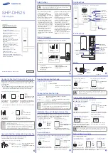
Page 4: ...d Confirm the door opening direction leftward or rightward inward or outward ...

Page 5: ...oor opening direction Refer to Article 3 of Chapter Preparing for installation 2 Handle adjustment a Leftward and rightward opening adjustment adjust the limit card screws to the position limiting the handle lifting b Clutch adjustment please adjust the clutch position firstly before installation as shown in the marks of the spindle Rotate the spindle paralleling to the handle for rightward openin...

Page 6: ...3 Install the batteries into the front handle The batteries are positioned on the handle of the front panel please loosen screws and install according ...

Page 7: ...ils 4 Install the spindle to the front handle use the spike fix the spindle on the clutch bending its pin prevents disengagement and adjust the direction of fixing spike according to the door opening direction Refer to picture in article 2 of this Chapter 5 Pass the front handle through the installed latch bolt with three holes pined and attention to the placement of rubber pad ...

Page 8: ...5 20 degrees long press or about 3 seconds until the blue indicator on and release the switch after 1 beep Press the finger to set at the center of the fingerprint area if the data is collected successfully the blue indicator will flash once and a beep will be sounded to remind that a fingerprint is acquired if there is a in proper input or failure the red indicator will flash once and tick two ti...

Page 9: ... of Chapter Preparing for installation and the Article 2 of Chapter Door lock installation The position of the card to the outer handle the parallel and vertical placement between the dowel pin and the handles of the quadrangular lock shaft as well as the door opening direction shall be set according to the installation instructions properly Please refer to the installation instructions for detail...

Page 10: ...ints Up to 40 fingerprints to store and each fingerprint shall be recorded for 5 times Power Consumption 25uA for standby and 200MA for actions Battery Alkaline batteries 4 Nos AAA by 1 5v Or four Ni MH Batteries Information Indicator Two color LED blue red and light with buzzer rotation Fingerprint setting Mechanical key to trigger setting switch by 15 degree clockwise switching Low voltage warni...

Page 11: ......

Reviews: