

HZ-KPCN
Horizon™ Keypads
Installation Guide
Description
Crestron
®
Horizon™ HZ-KPCN-series precision keypads provide optimal control of
Crestron devices such as lighting, shading, and A/V equipment from a single location.
Each keypad offers up to five tactile button or rocker switch positions, multicolor LED
backlighting, laser-engraved buttons and customizable faceplates designed to meet your
needs. Simply connect the keypad directly to your Cresnet
®
control network to begin.
Additional Resources
Visit the product page on the Crestron website (
)
for additional information and the latest firmware updates. Use a QR
reader application on your mobile device to scan the QR image.
Keypad Installation
NOTE:
Before operating the HZ-KPCN, ensure the device is using the latest firmware.
Check for the latest HZ-KPCN firmware at
firmware onto the device using Crestron Toolbox™ software.
The Horizon keypad is designed for installation into a standard, single-gang electrical box.
For larger applications, combine up to four keypads in a multi-gang electrical box.
To install the keypad:
1. Turn the system power off.
2. Place the backplate over the rear of the keypad.
NOTE:
Crestron recommends installing all keypads with the included backplate
for a more precise, consistent installation. However, when installing keypads in
retrofit electrical boxes, the backplate may be omitted.
3. Wire the keypad, connecting to the NET and INPUT ports as needed.
INPUT:
From contact closure or
non-system occupancy
sensor (e.g., GLS-ODT-C-NS).
NET:
Communications from control
system or daisy-chained
Cresnet device.
NET:
To daisy-chained Cresnet
®
network device.
4. Fold wires carefully into the back of the electrical box. Avoid pinched wires.
5. Position the keypad in the electrical box with the TOP label properly oriented and
secure the device to the electrical box using the provided screws.
CAUTION:
Do not overtighten the screws when attaching the keypad to the
electrical box, damage to the unit and undesired functionality may occur.
Top and
bottom trim
Keypad
Faceplate
Backplate
Drywall
Electrical box
6. Attach the magnetic trim plates to the top and bottom of the faceplate.
7. Ensure all buttons actuate without sticking.
8. Restore the system power.
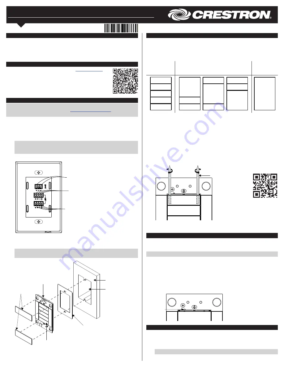
Button Configurations
The keypad button layout is configurable to suit a wide range of uses. Each keypad
includes five standard button positions, which may include a single pushbutton or
horizontal rocker switch cap. Larger vertical rocker switches are also available. All buttons
are intended to be laser-engraved to identify each button’s function.
The HZ-KPCN offers the following button-cap configurations:
Five Buttons:
HZ-BTN-1 or
HZ-BTN-RKR1
Three Buttons:
HZ-BTN-1 or HZ-BTN-RKR1 and
HZ-BTN-RKR3
One Button:
HZ-BTN-RKR5
• HZ-BTN-1: One-row button cap, center press (supplied - qty. 5)
• HZ-BTN-RKR1: One-row rocker button cap, left/right press (not supplied)
• HZ-BTN-RKR3: Three-row rocker button cap, top/bottom press (not supplied)
• HZ-BTN-RKR5: Five-row rocker button cap, top/bottom press (not supplied)
To replace keypad buttons:
1. Insert the flat end of the spudger tool between the button cap and the keypad near
the left edge of the button. Rotate the spudger tool clockwise to remove the left side
of the button cap.
2. Insert the flat end of the spudger tool between the button cap and the keypad near
the right edge of the button. Rotate the spudger tool counterclockwise to remove the
right side of the button cap.
Spudger tool
3. Align the posts on the back of the new button cap with the slot in the keypad and
press firmly onto the keypad. Ensure that the button cap actuates without sticking.
Ambient Light Sensor Calibration
Behind each button is an LED backlight, which illuminates the engraving. The ambient light
sensor adjusts the keypad’s backlight brightness according to the light level in the room.
Once the custom, laser-engraved buttons are installed, calibrate the ambient light sensor.
NOTE:
The LED backlight is enabled after light sensor calibration.
To calibrate the light sensor:
1. Ensure the faceplate and bottom trim piece are installed correctly. Remove the top
trim piece.
2. Press and hold the setup button using the pointed end of the supplied spudger tool
until all keypad backlights flash magenta (about 2 seconds).
3. Avoid blocking the light sensor. The light sensor should remain unobstructed and
free of direct light. After about 5 seconds, the calibration process is complete. The
keypad returns to normal operation.
Setup
button
Backlight Customization
To change the color of the LED backlights:
1. Press the setup button once using the pointed end of the spudger tool. The LED
backlights will light brightly for 15 seconds.
2. Press the setup button repeatedly to cycle through the backlight color options.
NOTE:
Custom color themes may be defined in the control system program.
Scan the QR
code to view a
video tutorial of
the button cap
replacement
process.


