quickstart guide
CCS-UC-100
www.crestron.com
888.273.7876
201.767.3400
Specifications subject to
change without notice.
Crestron RL™ Group Collaboration System for Lync
®
1
CCS-UC-100
For regulatory compliance information, refer to Doc. 7548.
1
Preparation
2
Installation
Typical CCS-UC-100 installation procedures are provided in
steps A through H. For detailed information about the
CCS-TS-6500 Tilting Wall Mount for 65” Display, refer to the
included CCS-TS-6500-WMK Installation Guide (Doc. 7511).
Alternate mounting procedures for the CCS-UC-CODEC-100
are provided in step I.
A. Verify Contents
Before starting installation, check the system package contents. Included items are listed in the
following table. Retain all documents and parts supplied for use in the installation process.
Crestron RL™ is a comprehensive group collaboration solution that combines Crestron
®
hardware with
Microsoft
®
Lync
®
software. The Crestron RL solution is based on Microsoft Lync 2013, a popular and
powerful server-based application that many companies already use on a daily basis. This full-featured,
unified communication system enables video, voice, interactive content sharing, presence, and chat from
one touch screen interface.
Two Crestron RL systems are offered. The dual display system (CCS-UC-100-2 KIT) is perfect for medium
to large conference rooms, and includes two high-definition 65" touch displays. The single display system
(CCS-UC-100-1 KIT) includes a single 65" touch display and is ideally suited for small to medium sized
conference rooms, executive offices, and huddle rooms.
.
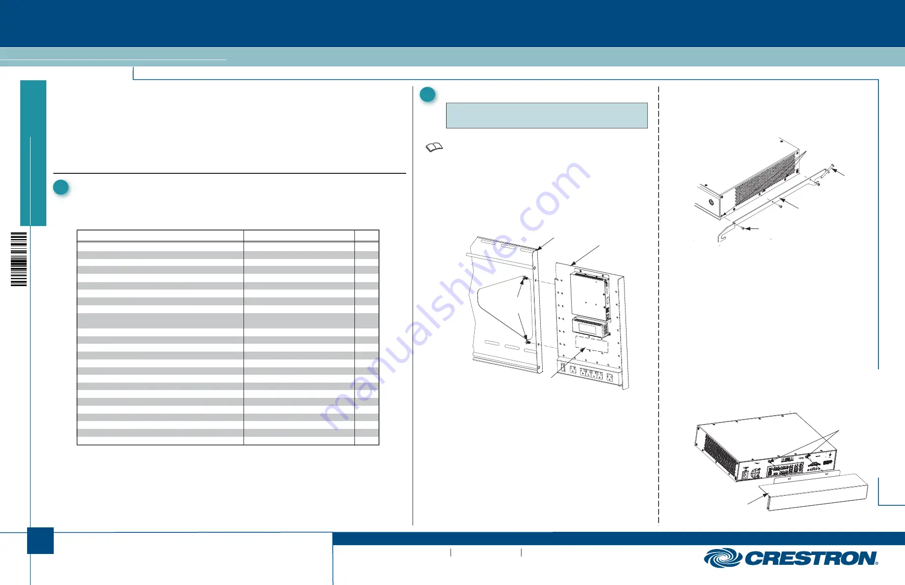
C. Install Cable Tray
Attach the supplied cable tray to the rear of the codec
as follows:
1. Attach all interface and power cables to the rear
of the codec, including those that connect to the
CCS-TX-201-C and PoE injector mounted on the
accessory bracket assembly. (Refer to the
connection details on page 3.)
2. Route the cables right or left toward their
intended termination point, and bundle them with
plastic tie wraps as necessary.
3. Loosen the two screws indicated in the illustration
below approximately 1/4” (6 mm).
4. Mount the cable tray on the screws, slide the tray
to the right to engage the keyhole slots, and
tighten the screws.
Cable Tray
Mounting
Screws
B. Install Mounting Brackets on Codec
1.
Remove three side cover bottom screws from each
side of the codec and discard them.
2.
Attach right and left codec mounting brackets to
codec using the supplied screws.
.
Screws
(3 Each Side)
Supplied
Codec Mounting
Bracket, Right
(Codec Mounting
Bracket, Left Not
Shown)
Side Cover Bottom
Screws
1.
Mounting hardware included.
2.
One in CCS-UC-100-1 KIT; two in CCS-UC-100-2 KIT
NOTE:
Mounting hardware is packaged with the parts and
assemblies to be attached.
2. Use two plastic tie wraps (supplied), to attach the power
supply for the 65” touch screen overlay to the accessory
bracket in the area indicated by the dashed line in the
illustration above. The port for the ac power source should
face to the right.
3. Cut the tie wraps securing the power strip cable to the
accessory bracket (secured for shipping only).
.
Wall Plate
Accessory
Bracket
Mounting
Screws
Attach Supplied
Long Screws
To Brackets
DESCRIPTION PART
NUMBER
QTY
Touch Screen, Color, 10”
TS-1051-C-B-S
1
Camera, USB, Fixed, 2 Megapixel
CCS-CAM-USB-F-100
1
CCS, Cable, Audio, 3.5 mm to (2X) RCA, 3’ (1 m)
CBL-AUD-3MM-RCA-3
1
CCS, Cable, Audio, 3.5 mm to (2X) RCA, 12’ (4 m)
CBL-AUD-3MM-RCA-12
1
Cable, VGA to DVI, 30’ (~10 m)
CBL-VGA-DVI-30
1
Cable, HDMI to DVI, 30’ (~10 m)
CBL-HD-DVI-30
1
Cable, HDMI to DVI, 3’ (1 m)
CBL-HD-DVI-3
1
Cable, HDMI to DVI, 20’ (~6 m)
CBL-HD-DVI-20
1
Cable, CAT6, 14’ (~4.3 m)
CBL-CAT6-14
1
CCS, Cable, Sleeve, Expandable, Wrap, 1/2” x 33”
CBL-SLEEVE-EXPAND-WRAP
2
(13 x 838 mm) L, Blk
1/2-33-B
Crestron Collab Sys, Unified Comm, Codec, MSLYNC
CCS-UC-CODEC-100
1
1
Crestron Collab Sys, SPK, Sound Bar, Blk
CCS-SPK-SB-100-B
1
Wall Mount Kit: CCS-TS-6500
CCS-TS-6500-WMK
1
1
Crestron Collab Sys, Touch Screen, 65” (1.65 m), 1080p, Blk
CCS-TS-6500-B
1
2
3 Cable Assembly
CBL-HD-ASSY
1
Accessory Bracket Assembly
CCSA-BRKT-100
1
1
Codec Mounting Bracket, Right
N/A
1
1
Codec Mounting Bracket, Left
N/A
1
1
Sound Bar Bracket
N/A
1
1
Camera Bracket
N/A
1
1
Cable Tray
N/A
1
1
Shelf Mount Bracket
Included with codec
1
Rack Mount Bracket
Included with codec
2
Power Pack For Ethernet
PWE-480SU
1
1’ (~0.3 m) LAN Cable
CBL-CAT6-1
1
A. Install Accessory Bracket Assembly
1.
Use the supplied 1/4-20 x 1/2” mounting screws to attach
the accessory bracket assembly to the wall plate (part of
the CCS-TS-6500).
Attach Power Supply
(Codec
Mounting
Brackets Not
Shown)
B. Tools Required
Installation requires the use of a #1 or #2 Phillips screwdriver as well as a socket wrench
with 1/2” and 7/16” sockets.
QUICKSTART DOC. 7479B (2035756, Sheet 1 of 2) 08.13
(Continued on following page)