Craftsman 536.88626, User Manual
The user manual for Craftsman 536.88626 is a comprehensive guide to understand and operate this outstanding product. It is available for download, completely free of charge, at manualshive.com. Access this manual to unlock the full potential of your Craftsman 536.88626 and ensure a seamless user experience.
Share
Download


Reviews:
No comments
Related manuals for 536.88626

BLV 36-240 Battery
Brand: Kärcher Pages: 224

Hotwind S
Brand: Leister Pages: 4

1693650 860M
Brand: Simplicity Pages: 26

KPB-6030
Brand: Keyang Pages: 15

262258
Brand: Silverline Pages: 28

189645
Brand: Poulan Pro Pages: 20

414949
Brand: Poulan Pro Pages: 52
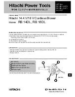
RB 14DL
Brand: Hitachi Pages: 16

GBL 620
Brand: Bosch Pages: 40

GBL 18V-120
Brand: Bosch Pages: 145

GBL 620 Professional
Brand: Bosch Pages: 37

GBL 860
Brand: Bosch Pages: 79

DHG602DUC
Brand: Bosch Pages: 24

GBL 82-270
Brand: Bosch Pages: 43

E600E
Brand: MTD Pages: 28

2750-AP
Brand: Holder Pages: 21

SB-M
Brand: Schmalz Pages: 2

SGBL-DG-1600-300-SO
Brand: Schmalz Pages: 6


