MANUAL
HUMIDIFIER CONTROL
24 VAC
SOLENOID VALVE
LEADS
HUMIDIFIER
24 VAC TERMINALS
ON FURNACE
NOTE:
CONNECT SOLENOID
VALVE TO HOT WATER IF
HUMIDIFIER WILL BE
OPERATED INDEPENDENT
OF HEATING CALLS.
HUMIDIFIER
TRANSFORMER
(FIELD SUPPLIED)
120 VAC
24 VAC
24 VAC
SOLENOID VALVE
LEADS
120 VAC “EAC”
TERMINALS
ON FURNACE
MANUAL
HUMIDIFIER CONTROL
(R) 24 VAC
HOT TERMINAL
WARNING: DO NOT CONNECT FURNACE HUM TERMINAL
DIRECTLY TO HUMIDITY SENSING THERMOSTAT HUM TERMINAL
INDOOR
EQUIPMENT
(HUM)
TERMINAL
HUMIDIFIER
HUMIDITY SENSING
THERMOSTAT
24 VAC
SOLENOID VALVE
LEADS
EQUIPMENT
CONTROLLER
HUMIDIFIER
INDOOR
UNIT
24 VAC
SOLENOID
VALVE
LEADS
HUMIDIFIER
INDOOR
UNIT
24 VAC
SOLENOID
VALVE
LEADS
READ COMPLETE SAFETY INSTRUCTIONS AND INSTALLATION TEMPLATE BEFORE STARTING
This product must be installed by a qualified heating and air conditioning contractor. Failure to do so could result in serious injury from electrical shock.
This product must be installed in compliance with all local, state and federal codes.
ATTENTION INSTALLER:
SBP SMALL BYPASS HUMIDIFIER
The humidifier can be installed on
either the supply or return plenum
of a forced air handling system and
is easily reversible for installation
with right hand or left hand bypass
duct connections. The humidifier
dimensions and serviceability must
be considered when selecting the
best location for the humidifier.
RETURN
RETURN
RETURN
SUPPLY
SUPPLY
SUPPLY
RETURN
RETURN
RETURN
SUPPLY
SUPPLY
SUPPLY
Horizontal
Upflow
90-1115
90-1116
90-1117
90-1118
90-1119
90-1079
WARNING
1.
ELECTRICAL SHOCK HAZARD.
Disconnect electrical power to the
furnace and install lock-out tag
before starting installation. Failure to
do so could result in serious injury
from electrical shock.
2.
SHARP EDGES HAZARD.
Sharp
edges may cause serious injury from
cuts. Use care when making plenum
openings and handling ductwork.
3.
RISK OF SCALDING.
Water
temperature over 125°F can cause
severe burns and scald instantly.
Shut off the hot water supply before
disconnecting or tapping into any hot
water supply line.
SPECIFICATIONS
HUMIDIFIER DIMENSIONS
Width
(including solenoid valve):
15
5
⁄
8
”
Height
(including drain spud):
13”
Depth
:
10
1
⁄
4
”
BYPASS DUCT OPENING
6” diameter
PLENUM OPENING
9
1
⁄
2
”W x 9
1
⁄
2
”H
WATER FEED RATE
3 gph
ELECTRICAL DATA
24 VAC-60 Hz, 0.5 AMP
CAUTION
1. Do not install humidifier where freezing temperatures
could occur. The water line could freeze and crack
causing water damage to the home.
2. Do not install humidifier or bypass connection on the
furnace cabinet.
3. Do not install humidifier or bypass connection on a
plenum face where the blanked off ends of the cooling
coil will restrict air movement through the humidifier.
4. Do not set humidity level above recommended or to
recommended level if condensation exists on inside
windows of any unheated space, as condensation
damage may result. Excess humidity can cause
moisture accumulation which can allow the possibility
for mold growth in the home.
5. Do not connect humidifier transformer to
blower motor wiring. Premature component
failure may result.
6. When installing Humidifier Control on downflow
furnace, ensure blower continues to run
after a heat call is satisfied to eliminate high
temperatures from damaging the Control.
7. Do not install humidifier where water pressure
exceeds 125 psi, since damage to the
humidifier may result. Follow codes in effect
concerning pressure reduction.
8. Do not install humidifier on systems with
greater than 0.4 in. wg pressure differential
between supply and return plenums.
RISK OF PROPERTY AND EQUIPMENT DAMAGE.
INSTALLATION OPTIONS
WIRING DIAGRAMS
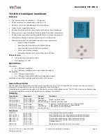
HumidiTrac
™
Automatic Humidifier Control
For detailed Automatic Humidifier Control
installation and wiring instructions,
see Form IM-AHC-03 included with Control.
DIAGRAM A
FOR OPERATION DURING “HEAT CALL” ONLY
DIAGRAM B
FOR OPERATION WHEN BLOWER IS ENERGIZED
DIAGRAM D
ZONING HOOK-UP
WITH EQUIPMENT CONTROLLER
DIAGRAM E
NEW COMMUNICATING CONTROL HOOK-UP
WITH ALL INDOOR EQUIPMENT
DIAGRAM C
FOR HUMIDIFIER OPERATION WITH HUMIDITY SENSING
THERMOSTAT
TEMPLATE MUST BE LEVEL
© 2018 CAC/BDP
7310 West Morris St., Indianapolis, IN 46231