Comtrol DeviceMaster Up, Hardware Installation Manual
The Comtrol DeviceMaster Up is a reliable and efficient device that allows seamless control and connectivity for your network. Enhance your user experience with our comprehensive and easy-to-follow User Manual, available for free download from manualshive.com. Explore the full potential of our product and empower your network management effortlessly!
Share
Download


Reviews:
No comments
Related manuals for DeviceMaster Up
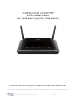
DSL-2740B
Brand: D-Link Pages: 10

51
Brand: IBM Pages: 248

EtherLink 3C509B
Brand: 3Com Pages: 8

3CRWB6096
Brand: 3Com Pages: 8

P1GCCAS
Brand: Garland Pages: 4

HPE-4S1
Brand: IEI Technology Pages: 3

SHIELD-2AMOTOR
Brand: Cytron Technologies Pages: 13

EG2013B-M11
Brand: Baicells Pages: 10

CDG561 WE~P21
Brand: Zalip Pages: 77

EtherFast LNE100TX ver. 5
Brand: Linksys Pages: 42

UT-300R2U
Brand: UTStarcom Pages: 71

LSWM12H2Q
Brand: H3C Pages: 9

CNPS5X PERFORMA
Brand: ZALMAN Pages: 8

Elinx EIR508 Series
Brand: B&B Electronics Pages: 2

SV1800 Series
Brand: Symantec Pages: 100

RK-1
Brand: Pakedge Device & Software Pages: 14

SH-GE90
Brand: Technics Pages: 20

Extreme Spirit Il
Brand: Thermaltake Pages: 2


