background image

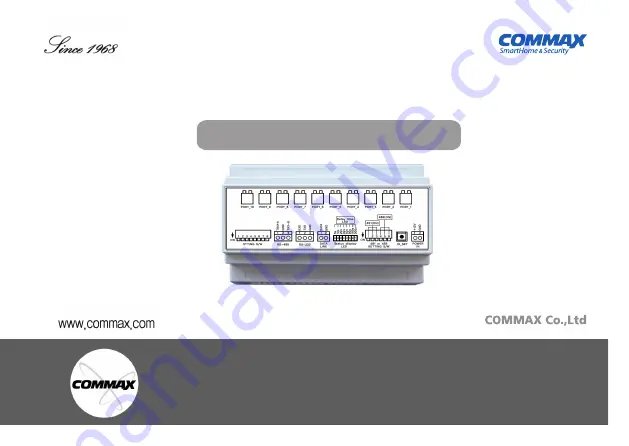
Elevator Call Device CCU-310EV

Product User Guide

Thank you for purchasing COMMAX products.

Please carefully read this User’s Guide (in particular, precautions for safety) before using a product and follow 

instructions to use a product exactly.

The company is not responsible for any safety accidents caused by abnormal operation of the product.

Summary of Contents for CCU-310EV

Page 1: ...asing COMMAX products Please carefully read this User s Guide in particular precautions for safety before using a product and follow instructions to use a product exactly The company is not responsible for any safety accidents caused by abnormal operation of the product ...

Page 2: ...ecaution 3 3 Name and Features of each part 4 4 Product Installation and Setting method 5 5 How to set the product for each mode 6 6 How it works 20 7 How to set household using PC 22 8 CCU 310EV Factory Reset 29 9 Wiring Diagram 29 10 Specification 32 ...

Page 3: ...se the unit to rain or moisture This symbol is intended to alert the use to the presence of uninsulated dangerous Voltage within the product s enclose that may be of sufficient magnitude to constitute a risk of electric shock to persons This symbol is intended to alert the use to the presence of important operating and maintemance servicing instructions in the literature accompanying the appliance...

Page 4: ...us damage to the appliance Any mounting of the manufacture s instructions and should use a mounting accessory recommended by the manu facturer Object and Liquid Entry Never push objects of any kind into this product through openings as they may touch dangerous voltage points or short out parts that could result in a fire or electric shock Never spill liquid of any kind on the product Lightning For...

Page 5: ...A connection terminal Κ Data Port 481 System DATA communication line port Λ Status LED LED for operation status check Μ 481 or 485 setting DIP switch 481 communication 1 2 3 ON 485 communication 4 5 6 ON Ν Call setting button Guard station calling button during CCU 310EV ID setting Ξ Power port DC power terminal DC adaptor 12V 1A EL connection port Connection port for EL calling button PORT_1 PORT...

Page 6: ...OFF S W2 Î OFF household floor mode S W1 Î OFF S W2 Î ON lobby mode S W1 Î ON S W2 Î OFF z DIP switch SETTING S W z This product is an elevator call device that can be linked with the lobby phone and the video phone according to the mode z DIP switch 481 or 485 SETTING S W 481 Mode S W1 2 3 Î ON S W4 5 6 Î OFF 481 Mode Home Auto System connection 481 Mode Please use after connecting 2P DATA commun...

Page 7: ...on in the household z The elevator call function is not supported when the door is opened by the lobby phone z Applicable for only specific video phone which provides EL call function z Household information must be registered in CCU 310EV to use EL calling z Only registered household can use EL calling z 1 unit of CCU 310EV can register up to 10 households z ID of CCU 310EV can be fixed from 1 to...

Page 8: ...1 ID setting method by DIP switch Ι Press ID SET button to call guard station Κ ID of CCU 310EV shown on guade station shown like 9501 XXXX ex If S W8 is ON shown like 9501 0001 Remark Ȅ Meaning of 9501 0001 9501 Serial number of CCU 310EV device household input mode household floor mode 0001 ID of CCU 310EV just set by DIP switch ...

Page 9: ... station by CCU 310EV ID_SET button 2 From guard station During calling Remote button Î 101 building No Î ミ Î 101 Room No Î Extension button Î 0 SUB No Î Î Call end Ȅ SUB Number SUB number is a port number that such household will use for EL calling SUB number can be set from 0 to 9 SUB number 0 9 means CCU 310EV s PORT_1 PORT_10 numbers Household input mode must be registered individually for eac...

Page 10: ...switch Household input mode S W3 S W 8 BOARD ID setting Please refer to the below instruction Number How to set up Number How to set up Number How to set up 1 2 3 Number How to set up Number How to set up Number How to set up 61 62 63 ...

Page 11: ...ion z Household s floor information must be registered in CCU 310EV to use EL calling z All households of the floor set by CCU 310EV can use EL calling 1 unit of CCU 310EV can register up to 10 floors up to 80 floors z It is used to set one floor per port of board Η Set DIP switch to be household floor mode When you call an elevator from a household S W1 Î OFF S W2 Î ON z ID of CCU 310EV can be se...

Page 12: ...e household input mode household floor mode 0001 ID of CCU 310EV Set by DIP switch Λ Setting household s building number and CCU 310EV s ID from guard station Ex 1 In case building 101 s CCU 310EV ID is 1 1 Call guard station by CCU 310EV ID_SET button 2 From guard station During calling status Remote button Î 101 Building No Î ミ Î 0001 ID No Î Î Call End Ȅ Registration complete Building 101 s ID ...

Page 13: ... EL calling button can be connected from 11th to 20th floor Î PORT_1 11th floor PORT_10 20th floor Ȅ The floor is automatically assigned as above when entering the ID two digits of the four digits of the household number Ex1 0101 0101 1st floor Designated ID_1 PORT_1 Ex 2 0101 0707 7th floor Designated as ID1_ PORT_7 Ex 3 0101 1109 11th floor Designated as ID_2 PORT_1 Ex 4 0101 2010 20th floor Des...

Page 14: ... 5 2 1 ID setting method by DIP switch Household Floor mode S W5 S W 8 BOARD ID setting Please refer to the below instruction Number How to set up Number How to set up Number How to set up 2 1 3 4 5 6 7 8 ...

Page 15: ...ceed after setting the household input mode on the lobby phone Household input mode on the lobby phone Program button Î Management password Î Bell button Î Program button Î 15 Î Bell button Lobby phone enters household input mode Press ID SET button on the CCU 310EV to call ID of CCU 310 is displayed on the lobby phone Input the ID No set by DIP S W Input serial number as 0 When the input is compl...

Page 16: ...on in the household z Before setting go to Program No 18 Connect SECUMAX and select Use 1 z Please use after connecting DATA communication DATA line connects to the Guard station DATA line Η Put ON of DIP switch 1 set CCU 310EV to be lobby mode S W1 Î ON S W2 Î ON In case Secumax is not installed When calling the elevator from the lobby phone S W1 Î ON S W2 Î ON In case Secumax is installed ...

Page 17: ...D set by DIP switch Μ The ID of CCU 310EV changes z CCU 310EV 1 unit one ID can cover 10 units of lobby phones 10 buttons of EL call Ex 1 Connect CCU 310EV ID 1 to the product serial number XXXX 9901 XXXX 9910 If you connect a lobby phone to CCU 310EV ID 1 product in 101 you can connect up to ten Lobby phones sequentially from 0101 9901 to 0101 9910 Ex 2 Connect CCU 310EV ID 2 to the product seria...

Page 18: ...utton to PORT_1 PORT_10 which is the same ID of installed lobby phone Ex 1 1st floor s Lobby ID is 101 9901 Connect EL calling button to PORT_1 Ex 2 Basement 1st floor s Lobby ID is 101 9902 Connect EL calling button to PORT_2 ...

Page 19: ... it works when opening the door during calling between LOBBY and household If no intalled SECUMAX calling might be calling problem due to lots of data stored into the lobby Î If no SECUMAX S W2 must be ON to respond the data instead of SECUMAX z S W3 S W4 NONE USED z S W5 S W8 CCU 310EV ID setting S W5 BIT3 S W6 BIT2 S W7 BIT1 S W8 BIT0 LOBBY MODE ID1 ID9 can be set Ex 10 LOBBY is set per one CCU ...

Page 20: ...5 3 1 CCU 310EV ID setting method by DIP switch Lobby Mode S W5 S W 8 BOARD ID setting Please refer to the below instruction Number How to set up Number How to set up Number How to set up 2 1 3 4 5 6 7 8 9 ...

Page 21: ...household s floor LED of the port is tuered on 6 2 EL calling method when lobby mode z Only applicable for lobby phone which CCU 310EV setting is completed Press door open button during calling between lobby and household Î EL is automatically called to the floor in which the lobby phone is located In case main entrance is open by password Î EL is automatically called to the floor in which the lob...

Page 22: ...ng diagram Press the ID SET button for 3 seconds After the LEDs flash sequentially the LED at the previously set position blinks The delay time can be changed to 5 10 20 30 50 90 180 300 seconds When the delay time is set press the ID SET button again for 3 seconds All LEDs blink sequentially and the LED changes to the operating state If there is no input for 30 seconds during setup it will exit a...

Page 23: ...set C Select the COM port for RS232 communication D Select Speed as 115200 E Click Port Open F Select Household Data Management G If you select Inport Data from Device the setting value of CCU 310EV will appear on the display Î The household information assigned to each terminal is displayed as shown below You can change directly after clicking the household information of the terminal Only change...

Page 24: ...23 A ...

Page 25: ...24 B C D E F ...

Page 26: ...25 G ...

Page 27: ...26 ...

Page 28: ...e CCU 310EV Household information request The household information stored in the CCU 310EV is showed to the display monitor 2 Data Management Use to backup or read household information in a separate file Load Household Information Loads the backed up DATA file MDB file Save Household information Create backup file by saving current DATA MDB file 3 Password batch change Do not use 4 Building Hous...

Page 29: ...ar Terminal No Reset This function is used to rearrange the terminal numbers if they are not read in order 6 End Close Program mode CCU 310EV becomes standby mode After modifying the information remove the RS 232 port after exiting Note If you remove the port without shutting down the CCU 310EV is in program mode and will not operate normally Ȅ In order to insert DATA into CCU 310EV after using th...

Page 30: ...ethod is to turn off the power turn off or turn on all of the dip switches S W1 to S W8 and turn on the power LED quickly and the information will be initialized z All settings apply the status of S W at power on 9 Wiring Diagram 9 1 Wiring Diagram ...

Page 31: ...ing method when household floor mode Set the lobby mode for lobby interlocking Refer 5 3 Setting method when using in Lobby mode 30 9 2 Wiring method In case of interworking with Home auto system Connect 2 lines of DATA line to DATA line of Home Auto System Connect the two contact port wires corresponding to each floor to the call button of the elevator on each floor ...

Page 32: ... System interlocking 7 household such as how to set up a household using a PC and lobby information Connect the contact port 2 of the registered lobby or household to the call button of the elevator on the corresponding floor of the lobby or household Connect three lines of RS 485 to the RS 485 line of the Home Network System Refer to the manual of home network system lobby phone or monitor for th...

Page 33: ...ame Spec CCU 310EV Wiring 481 DATA 2 lines Polarity E V connection 2 lines Non polarity Voltage DC 12V 1A Power Consumption Standby 55mA Operation 70mA Distance 1Km Pie 0 65 wire basis Operating Temp 0 40 RS 485 3 lines Polarity ...

Page 34: ...Printed In Korea 2018 10 105 513 11 Sangdaewon dong Jungwon gu Seongnam si Gyeonggi do Korea Int l Business Dept Tel 82 31 7393 540 550 Fax 82 31 745 2133 Web site www commax com ...

Reviews: