Coastal MK II Digital Thermostat/Thermometer
(1) Description
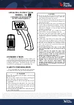
The Coastal MK II Digital Thermostat/Thermometer comprises of a thermostat unit
mounted in a plastic mounting plate measuring 3.5” x 2”. The front panel incorporates a
three-digit red LED display with five-button control panel. The display shows degrees and
tenths of degrees, and can be set to work in either Fahrenheit or Celsius. The assembly is
pre-wired with a fused 10’ cable harness and push-on connectors to facilitate easy
installation. A 10’ temperature sensor probe is pre-wired, and the mounting plate is drilled for
the black screws provided.
(2) Location
The thermostat is designed to be mounted on a vertical surface, secured with the screws provided. Care must be taken to
ensure that the location chosen will not subject the panel or its components to splashing or running water, steam, corrosive gasses,
excessive vibration, or physical damage. Ideally the location will allow the 10’ thermostat sensor to be installed without being
extended. If it is necessary to extend the sensor cable, the electrical joints should be soldered. The thermostat requires a cut-out of
3.25” x 1.5”, and a minimum depth of 2-1/2”.
(3) Temperature Sensor Probe Mounting
The temperature sensor probe is mounted in the refrigerator or freezer cabinet so that it senses the average air
temperature.
It does not attach to the evaporator
. It is best mounted at mid-height, on a wall or divider that does not have any
part of the evaporator mounted on it, and insulated from the wall to ensure that it senses air temperature only.
(4) Operation
The Coastal MK II will display box temperature continuously. When the box warms up to a temperature of two degrees
above the set point (default), the thermostat will start the compressor. This will be signified by the illumination of a yellow snowflake
symbol on the display. When the system has lowered the temperature to the set point, the compressor is stopped and the snowflake
symbol extinguished. NOTE: The raindrop and light bulb buttons are inoperable and have no function on this thermostat.
(5) Turning on and off.
Press and hold SET and DOWN buttons for 8 seconds. “OFF” is displayed when turned off.
(6) Adjusting Temperature Set Point
The Coastal MK II is supplied set as a refrigerator thermostat in degrees Fahrenheit, with 40F as the set point. If installed on a
freezer system it is suggested to set the initial set point to 12F (-12C)
To change temperature set-point:
•
Press SET button. "SET" appears in display.
•
Press SET button again. Set point value is displayed and flashes.
•
Press UP or DOWN arrows to the desired set-point. Suggested starting set-points are 40F (4C) for a refrigerator, and
12F (-12C) for a freezer.
•
Press SET button. “SET” is displayed
•
Press SET and DOWN buttons together to quit and return to temperature display, or display will revert automatically in
one minute.
NOTE: Allow sufficient time for the system to settle down between making adjustments. At least one day is recommended.
(7) Fault Code Display
•
“ooo”
Temperature Sensor Probe or its cable is open circuit or disconnected.
•
“---“
Temperature Sensor Probe or its cable is short circuit
•
“ALH”
Buzzer will also sound. High temperature alarm has been activated. See
(10)
•
“ALL”
Buzzer will also sound. Low temperature alarm has been activated. See
(10)
(8) Emergency Operation if Temperature Sensor Probe Fails
If the Temperature Sensor Probe becomes either short circuit or open circuit, the Coastal MK IIa will show an alarm on the
display, see
(7)
.
There is an option to run the compressor on an emergency on-off routine according to time settings entered by the
operator. This feature is disabled, but can be activated by entering the desired “on”
and “off” times in c2 and c3 of the Con menu. See
(12)
(9) Wiring
1
2
4
5
7
8
DC Power Supply
Terminal “C” on Danfoss controller or Merlin
Terminal “T” on Danfoss controller or Merlin
Temperature Sensor
Rear view of Coastal MK II
NOTE:
A Power Terminal Multiplier is provided
to be installed on the + and – terminals
of the Danfoss controller. This provides a
second set of terminals for the red and
black power supply wires to connect to.
+
-
If using to control a spillover fan
:
Do not connect wires to controller.
Bridge terminals 4 and 7.
Connect black or blue fan wire to 5.
Connect red fan wire to 8.
Wires in 10’ harness