background image

CLEARSPAN

 FABRIC STRUCTURES

1

Revision date: 06.10.11
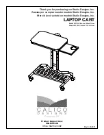
ClearSpan

 Storage Master 

Curved-Wall

Photo may show a model of a different length.

©2011 ClearSpan™

All Rights Reserved. Reproduction 

is prohibited without permission.

STK#   

     DIMENSIONS

104492W10      22' W x 20' L

104493W10      22' W x 30' L

104494W10      22' W x 40' L

104495W10      22' W x 50' L

Summary of Contents for 104492W10

Page 1: ...Span Storage Master Curved Wall Photo may show a model of a different length 2011 ClearSpan All Rights Reserved Reproduction is prohibited without permission STK DIMENSIONS 104492W10 22 W x 20 L 104493W10 22 W x 30 L 104494W10 22 W x 40 L 104495W10 22 W x 50 L ...

Page 2: ...e of the structure Failing to anchor the shelter properly will void the manufacturer s warranty and may cause serious injury and damage LOCATION Choosing the proper location is an important step before you begin to assemble the structure The following suggestions and precautions will help you determine whether your selected location is the best location Never erect the structure under power lines ...

Page 3: ...s before you begin to assemble your shelter Conduit An assembly of pipes used to secure the main cover and end panels if equipped Purlins and some strut assemblies also consist of connected pipes to form a conduit Each pipe joint of a conduit assembly is secured with a self tapping Tek screw Coupler or Fitting A part of the frame assembly where legs purlins and rafter pipes are inserted and secure...

Page 4: ...sary parts before you begin 1 Unpack the contents of the shipment and place where you can easily inventory the parts Refer to the Bill of Materials Spec Sheets 2 Verify that all parts listed on the Bill of Materials Spec Sheets are present If anything is missing or you have questions consult the Pictorial Parts Guide and all shelter diagrams throughout these instructions for clarification or conta...

Page 5: ...ome parts are not shown Pictorial Parts Guide FA4482B Tek Screw QH1061 Ratchet 100441 Nut Setter 103620 Nylon Strap AS1103 Cable Thimble AS1003 Cable Clamp 102676 Ground Post 102547 Cross Connector CC6214 Fabric Clip 104074 Square to Round Bracket QH1404 Band Camp 102857 Purlin End Clamp QH1070 Pipe Strap 103043 and QH1308 Strut QH1072 Post Driver QH1330 Frame Bracket 105944 Adjustable Tee GW1172 ...

Page 6: ...g For details of each assembly procedure consult the Quick Start Guide and the individual sections of these instructions See illustration below to identify main parts of the building 1 Select a location for the building 2 Identify the parts for each assembly procedure 3 Assemble all rafters and the frame Anchor the frame 4 Install the struts and cable assemblies 5 Prepare and install end panels an...

Page 7: ...e building to be square 7 Check all dimensions and adjust if needed before driving the remaining posts to the required height 8 After all corner posts are accurately installed tie a string line between the tops of the corner ground posts on the same side of the shelter The string is used to identify the tops of all remaining ground posts The string must remain tight and level 9 Determine which sid...

Page 8: ...shown above may differ from your shelter Diagram used for illustration purposes only 13 Verify that the on center width of the frame is uniform between the corner ground posts NOTE The frame is square when the two diagonal measurements are the same After the rafters have been assembled the rafter ends are secured to the ground post using the upper hole 14 Continue with the Rafter Assembly steps th...

Page 9: ... assemble the first end rafter and arrange on a level surface 2 Slide four 4 purlin end clamps and four 4 band clamps onto the curved pipes in the positions shown NOTE Position the purlin end clamps with the open side toward the outside of the building 3 Use a piece of duct tape to hold the purlin end clamps and band clamps in position until the rafter is erected 4 After slipping the clamps onto t...

Page 10: ...lain end of another 2 Drive a Tek screw into each pipe joint 3 Assemble the remaining rafter legs using the previous steps and the Quick Start Guide 4 On the straight wall side carefully stand the first rafter leg slide a band clamp onto the leg and place the drilled end of the leg pipe onto the first ground post NOTE Brace the leg in place to keep it straight Additional assistants may be needed C...

Page 11: ...ing the plain shorter 1 90 pipe 190P0XX 3 Slide the assembled pipe through the adjustable tees on the rafter legs As you insert the pipe through the fittings slip adjustable tees and band clamps onto the door header in the approximate locations shown in the diagram at the bottom of the page ATTENTION Where two 2 adjustable tees meet on the door header position them so they mate as shown 4 Drive a ...

Page 12: ...talled on the door header ATTENTION Stand the rafter so the nuts and bolts of the end clamps are to the inside of the frame NOTE The adjustable tees for the rafter ends and rafter legs must overlap as shown in the drawing below End Rafter Curved Pipe Section Door Header End Rafter Leg End Rafter Adjustable Tees 3 Secure the leg pipe to the ground post using the 5 16 x 2 1 2 machine bolts and nuts ...

Page 13: ...assembly and set it in position DO NOT USE THE REMAINING END RAFTER FOR AND INTERIOR RAFTER 17 Secure the rafter legs to the ground post and adjustable tee fitting as previously described and steady the rafter 18 Take another section of 1 315 purlin pipe 131S075 and attach to the rafter as previously described 19 Verify that the distance between the interior rafters is 60 center to center Adjust t...

Page 14: ...id the manufacturer s warranty and may cause serious injury and damage Strut 103043 Door Header END WALL INSTALLATION Refer to the end frame diagrams Quick Start section The materials and parts needed to assemble the end wall frame include Square tubing 102897 Square tubing S15P075 Square tubing S15P068 Square tubing S15P062 Square tubing S15P042 Angle brackets QH1330 band clamp QH1404 Square to r...

Page 15: ...e tube and attach the bracket to the tube using a nut and carriage bolt 11 With the square to round tube connect bracket attached to the top of the vertical door frame tube use the bolt in the band clamp to attach the bracket to the band clamp DO NOT TIGHTEN AT THIS TIME NOTE The head of the bolt is to the outside of the shelter At this point the vertical frame members should be loosely attached t...

Page 16: ... the QH1308 7 struts 2 Position the upper end of one strut on the end rafter leg about 4 above the base rail as shown below 3 Connect the strut to the rafter leg using the band clamp and carriage bolt previously attached to the rafter leg 4 From the inside of the building drive a Tek screw through the hole in the strut and into the base rail 5 Repeat steps for the remaining strut and install strut...

Page 17: ...n the previous steps NOTE Position the Tek screw head toward the inside of the building 2 Using the diagram below and the Side Profile diagrams in the Quick Start section as guides position a purlin on the inside of the frame diagonally and secure each end to the rafter with pipe straps and Tek screws Tek Screw 3 Verify that the diagonal frame brace is in the correct position and secure the frame ...

Page 18: ...imble 5 Install an additional cable clamp a few inches from the first clamp and tighten both clamps to secure the cable to the turnbuckle 6 Loop the remaining end of the 4 cable over the rafter leg union at the front of the building Consult the Side Profile Diagrams in the Quick Start section for your building to identify where to secure the cables NOTE Photo shows a building having a center rafte...

Page 19: ...le 9 Cut the remaining bulk cable into two 2 equal pieces 10 Feed the end of one cable through the turnbuckle eyelet and around the thimble to form a 10 loop 11 Install two 2 cable clamps to secure the cable and tighten the clamps ATTACH END WALL RATCHETS Consult the End Framing diagrams in the Quick Start section for the correct ratchet locations for your building Gather the parts Ratchets QH1061...

Page 20: ... end panel Repeat the steps to assemble the remaining end conduit 3 Unfold the end panel and place next to the frame Position the end panel with the conduit pocket surface up NOTE Install the end panel with the conduit pocket toward the inside of the building 4 Slide the assembled conduit into the end panel pocket 5 While standing inside the shelter start at the peak of the end rafter and pull the...

Page 21: ...amage the contents of the shelter To purchase the optional front roll up kit for your shelter contact Customer Service at 1 800 245 9881 for additional information If you do not have a front roll up kit to install continue by installing the ratchets WARNING To prevent damage to the panel and to prevent serious personal injury DO NOT attempt to install the roll up panel on windy days The following ...

Page 22: ...rews See diagram below Evenly space the clips as needed IMPORTANT Position the clips on the underside or backside of the door header pipe so that the head of the Tek screw does not touch the main cover Inside View Fabric Clips INSTALL ROLL UP ASSEMBLY Gather the parts Pipe 1 315 x 75 131S075 Pipe 1 315 x 49 5 131P0495 Spin handle 103395 Universal joint 103396 Fabric clips CC6212 1 Move to the roll...

Page 23: ...e can be trimmed to the desired length INSTALL ROLL UP ASSEMBLY continued MAIN COVER RATCHETS Straight Side Consult the Side Profile diagrams for the correct ratchet locations IMPORTANT If you have installed the optional front roll up kit roll the panel down Ratchets will be attached over the front roll up panels in the locations shown below Gather the parts Ratchets QH1061 Tek screws Complete the...

Page 24: ...n the ratchet about 6 in from the end of the conduit Repeat this step at the other end of the frame 2 Attach one 1 ratchet on the inside of each end rafter leg a few inches below the strut clamps If the optional front panel is installed attach the ratchet to the rafter through the panel See Step 1 Diagram below shows ratchet position when no front panel is installed 3 On the curved wall side attac...

Page 25: ...r pipe identification if needed b Insert the swaged end of each pipe into the plain end of another pipe until the conduit is assembled c Secure each pipe joint with a Tek screw ATTACH MAIN COVER Gather the Parts Main cover with conduits already inserted Ropes long enough to reach over the frame provided by customer Box cutter or utility knife Assembly Procedure 1 To pull the cover over the frame a...

Page 26: ... One person is required at each rope 4 Once the main cover is pulled into position center the cover on the frame and remove the ropes Loosely secure the ends of the cover to the ratchets attached to the end rafter legs and base rails ATTENTION Do not tighten the straps at this time 5 Lift the cover skirt curved side of the frame and cut a slit in the cover conduit pocket at the rafter position Ins...

Page 27: ... Lower the panel to allow it to dry and for cleaning if equipped Replace anti billow strap immediately if worn or broken if equipped Remove debris and objects that may accumulate on the shelter Use tools that will not damage the cover when removing debris Remove snow to prevent excess accumulation Use tools that will not damage the cover when removing snow Check the contents of the shelter to veri...

Page 28: ...T GUIDE 22 Wide Curved Wall Storage Master Building 22 4 3 4 Width 14 1 9 16 Height 10 1 1 8 Endwall Height Grid Represents 12 Squares END Frame shown may differ in length from actual frame Ground Level End End Curved Side of the Frame Straight Side of the Frame 24 ...

Page 29: ...901D 26R1901 26R1901 26R1902 105944 Adjustable Side Outlet 190P024 190S099D Ground Level End Rafter 102857 Mid Rafter 102547 End Rafter 102857 Mid Rafter 102547 End Rafter 102857 Mid Rafter 102547 End Rafter 102857 Mid Rafter 102547 102676 Ground Post 102676 Ground Post 24 ...

Page 30: ...r Door Header Run 190S099 190S099 190P048 Purlin Run Diagonal Frame Brace Diagonal Frame Brace Ratchets are attached to the rafters labeled with R R R R R R R 131S075 131S075 131S075 131P0735 131S075 131P0255 On Center Rafter Spacing 5 0 20 0 Length Center to Center Ground Level Front Roll Up Assembly if equipped 103395 103396 3 131S075 131P0255 131P0495 131S075 24 24 Attach Cable Ends Here See Pa...

Page 31: ...WALL On Center Rafter Spacing 10 0 30 0 Length Center to Center Purlin Run 131S075 131S075 131S075 131S075 131P0735 Ground Level Door Header Run 190S099 190S099 190S099 190P072 R R R R Ratchets are attached to the rafters labeled with an R Attach Cable Ends Here See Pages 18 19 24 24 ...

Page 32: ...L On Center Rafter Spacing 5 0 30 0 Length Center to Center Ground Level R R R R R Diagonal Frame Brace 131S075 131P0735 Diagonal Frame Brace Front Roll Up Assembly if equipped 103395 103396 4 131S075 131P072 131P0495 131S075 Ratchets are attached to the rafters labeled with an R 24 24 ...

Page 33: ...Center Rafter Spacing 40 0 Length Center to Center 190P096 Purlin Run 131S075 131S075 131S075 131S075 131S075 131S075 131P0495 Door Header Run 190S099 190S099 190S099 190S099 Ground Level R R R R R Ratchets are attached to the rafters labeled with an R Attach Cable Ends Here See Pages 18 19 24 24 ...

Page 34: ... 0 On Center Rafter Spacing 40 0 Length Center to Center Ground Level R R R R R R R Diagonal Frame Brace 131S075 131P0735 Diagonal Frame Brace Front Roll Up Assembly if equipped 103395 103396 6 131S075 131P0495 131P0495 131S075 Ratchets are attached to the rafters labeled with an R 24 24 ...

Page 35: ...cing 50 0 Length Center to Center Ground Level Ratchets are attached to the rafters labeled with an R R R R R R R 190P024 Door Header Run 190S099 190S099 190S099 190S099 190S099 190S099 Purlin Run 131S075 131S075 131S075 131S075 131S075 131S075 131S075 131S075 131P0255 Attach Cable Ends Here See Pages 18 19 24 24 ...

Page 36: ... On Center Rafter Spacing 50 0 Length Center to Center Ratchets are attached to the rafters labeled with an R R R R R R R R R R Diagonal Frame Brace 131S075 131P0735 Diagonal Frame Brace Front Roll Up Assembly if equipped 103395 103396 8 131S075 131P0255 131P0495 131S075 Ground Level 24 24 ...

Page 37: ...URES 37 Revision date 06 10 11 CONNECTIONS End Rafter Purlin Connection View 1 Mid Rafter Purlin Connection View 2 Rafter Door Frame Connection View 3 Rafter Strut Connection View 4 G r o u n d L e v e l G r o u n d L e v e l ...

Page 38: ...90 Band Clamp 102857 Purlin End Clamp Rafter Door Framing 105944 Adjustable Side Outlet Rafter Purlin 102547 Purlin Cross Door Framing Strut End Rafter Purlin Connection View 1 Mid Rafter Purlin Connection View 2 Rafter Door Frame Connection View 3 Rafter Strut Connection View 4 Door Header 103043 ...

Page 39: ...1 Rafter Endwall Connection View 2 Baserail Endwall Connection View 3 Rafter Support Connection End Wall Rafter Connection View 1 102897 102897 102897 S15P075 S15P062 S15P068 S15P042 102897 102897 Rafter Support Connection View 3 Endwall Base Rail Connection View 3 7 Strut QH1308 5 7 3 4 Center to Center 11 2 3 8 Center to Center 5 7 3 4 Center to Center End Cover Conduit 131S075 131S075 131S075 1...

Reviews: