CLASSIC INSTRUMENTS
ADJUSTABLE FUEL LEVEL SENDER KIT
SN35
(240
Ω
-33
Ω
),
SN36
(0
Ω
-30
Ω
),
SN38
(0
Ω
-90
Ω
),
SN39
(75
Ω
-10
Ω
) &
SN40
(10
Ω
-180
Ω
)
A = Tank Depth , B = Float Pivot Depth , C = Float Arm Length
(Dimensions in Inches)
A B C A B C A B C
6.0 3.0 3.5
12.0 6.0 7.8 18.0 9.0 12.0
6.5 3.25 3.8 12.5 6.25 8.1 18.5 9.25 12.3
7.0 3.5 4.2
13.0 6.5 8.5 19.0 9.5 12.6
7.5 3.75 4.5 13.5 6.75 8.9 19.5 9.75 12.9
8.0 4.0 4.9
14.0 7.0 9.3 20.0 10.0 13.4
8.5 4.25 5.3 14.5 7.25 9.6 20.5 10.25 13.8
9.0 4.5 5.6 15.0 7.5 10.0 21.0 10.5 14.2
9.5 4.75 6.0 15.5 7.75 10.4
10.0 5.0 6.4 16.0 8.0 10.7
10.5 5.25 6.7 16.5 8.25 11.0
11.0 5.5 7.1 17.0 8.5 11.4
11.5 5.75 7.4 17.5 8.75 11.8
TABLE 1
I.
Measure depth of the fuel tank. Locate this dimension in Column “A’’ of Table 1. Column “B” shows the length from the
underside of the sender flange to the center of the float pivot. Column “C’’ shows distance from the center of the float pivot to
the center of the float. For example, a tank 12’’ deep would need a measurement of 6’’ from the flange to the pivot and 7.8’’
from the pivot to the float.
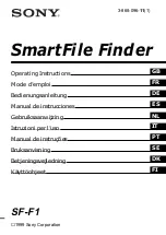
II.
For tank depths 6” to 15-1/2’’, it will be necessary to eliminate a part of the assembly. (See Fig.1) proceed as follows:
1. Remove two screws “d’’ and discard.
2. Remove two screws “e” from the plastic housing and reserve for later us.
3. Carefully remove bracket “f ’’ from the plastic housing and discard. Replace with bracket “g’’
in the housing and loosely re-install the two screws “e’’ into housing.
(6” tanks require mounting
rheostat with float toward the outside of the mounting bracket and use of only lower ”e” screw to fit)
4. Slide housing up or down until the proper dimension from Table 1 is reached, then tighten
screws securely.
CAUTION:
Do not over tighten hardware to avoid damage to the threads.
3.0000
6" Tank Rheostat Mounting