background image

MS210 Series Installation Guide

About this Guide

This guide provides instruction on how to install and configure your MS210 series switch. This guide also provides
mounting instructions and limited troubleshooting procedures. For more switch installation guides, refer to the

switch installation guides section

on our documentation website.
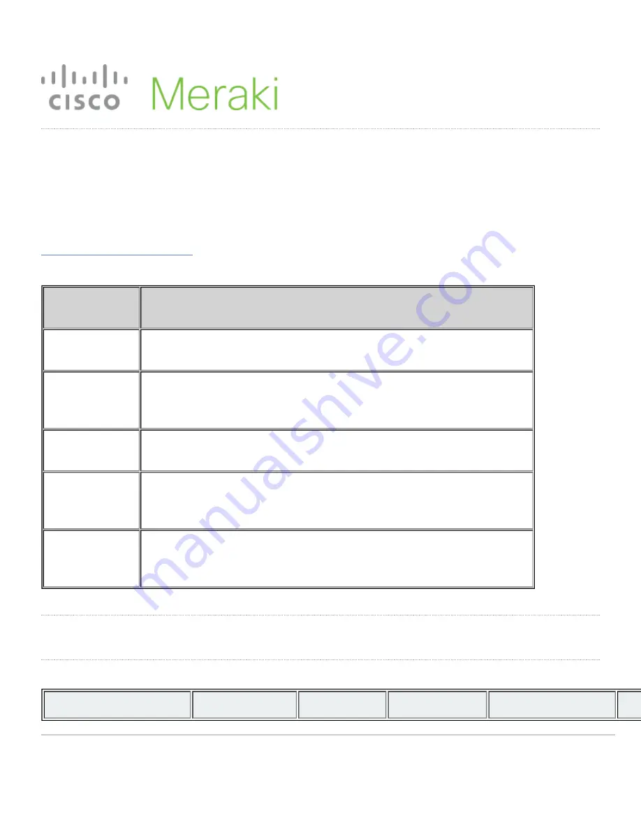
Model number

Description

MS210-24

Stackable Layer-2 24-port gigabit Ethernet switch with 4 SFP interfaces

MS21024P

Stackable Layer-2 24-port gigabit Ethernet 370W PoE switch with 4 SFP
interfaces

MS210-48

Stackable Layer-2 48-port gigabit Ethernet switch with 4 SFP interfaces

MS210-48LP

Stackable Layer-2 48-port gigabit Ethernet 370W PoE switch with 4 SFP
interfaces

MS210-48FP

Stackable Layer-2 48-port gigabit Ethernet 740W PoE switch with 4 SFP
interfaces

Product Overview

Physical Specifications

MS210-24

MS210-24P

MS210-48

MS210-48LP

MS210-48FP

1

Содержание Meraki MS210 Series

Страница 1: ...l number Description MS210 24 Stackable Layer 2 24 port gigabit Ethernet switch with 4 SFP interfaces MS21024P Stackable Layer 2 24 port gigabit Ethernet 370W PoE switch with 4 SFP interfaces MS210 48 Stackable Layer 2 48 port gigabit Ethernet switch with 4 SFP interfaces MS210 48LP Stackable Layer 2 48 port gigabit Ethernet 370W PoE switch with 4 SFP interfaces MS210 48FP Stackable Layer 2 48 por...

Страница 2: ...nal Fixe Power Input 100 240 VAC 47 63 H 100 240 VAC 47 63 Hz 100 240 VAC 47 63 Hz 100 240 VAC 47 63 Hz 100 Hz Power Consumption 15 882W 15 882W 15 882W 15 882W 15 Power Load idle max 15 24 W 21 448 W 25 42 W 53 490 W 54 Operating Temperature 23 F 122 F 5 C 50 C 23 F 122 F 5 C 50 C 23 F 122 F 5 C 50 C 23 F 122 F 5 C 50 C 23 5 C Storage and Transportation Temperature F and C F and C F and C F and C...

Страница 3: ...ot include stacking cables Stacking cables sold separately Product View and Physical Features Front Panel MS210 24 Series front panel MS210 48 Series front panel Back Panel MS210 Series back panel Ports and Status Indicators The MS uses LEDs to inform the user of the device s status When the device powers on all the Internet LEDs flash twice Additional functions are described below from left to ri...

Страница 4: ...ocal configuration settings Switch Ports Off No link is detected on this port Solid orange 10 100 Mbps Solid green 1 Gbps In addition there is a RESTORE button available on the front panel Insert a paperclip if a restore is required A brief momentary press To delete a downloaded configuration and reboot Press and hold for more than 10 sec To force the unit into a full factory restore Back Panel Co...

Страница 5: ...dant Power Supply Optional The MS210 series supports connecting the Cisco RPS2300 for optional power redundancy MS210 series models support failover and reversion to main power once it has been restored The following Cisco part numbers are supported Part number Description PWR RPS2300 RPS Chassis C3K PWR 750WAC 750W RPS Power supply C3K PWR 1150WAC 1150W RPS Power supply CAB RPS2300 E RPS 22 pin c...

Страница 6: ...he device with the provided power cables to ensure regulatory compliance Pre install Preparation You should complete the following steps before going on site to perform an installation Configure your Dashboard Network The following is a brief overview only of the steps required to add a switch to your network For detailed instructions about creating configuring and managing Meraki networks refer t...

Страница 7: ...witch Other features of the network such as 802 1X authentication may rely on the property that the switches have static IP addresses Static Assignment Static IPs are assigned using the local web server on each switch The following procedure describes how to set the static IP 1 Using a client machine e g a laptop connect to the switch over a wired connection 2 Using a web browser on the client mac...

Страница 8: ...t within the box This pamphlet contains detailed step by step guides and images to assist in the physical install of the switch 1 Install the mounting cage nuts in the rack being used for the switch 2 Separate the rack mount rails and install the rack mount rails channel onto the rack 8 ...

Страница 9: ...3 Attach the rack mount rail to the sides of the switch 9 ...

Страница 10: ...4 Insert the rack mount rail into the rack mount rail channel 10 ...

Страница 11: ...5 Attach the switch face plate to the cage nuts on the rack 11 ...

Страница 12: ...6 Secure the rack mount rail to the rack mount rail channel 12 ...

Страница 13: ...g hardware includes a rack mount kit for standard 1U racks When installing the device make sure that there is sufficient space between the rear of the rack and other obstacles to ensure adequate airflow Optional Mid Mount bracket MS210 48 port models are designed for an optional MA MNT MID 1 mid mount bracket when using 2 post racks 13 ...

Страница 14: ...s and additional information about stacking can be found here Reference https documentation meraki com MS for additional information and troubleshooting tips If you are still experiencing hardware issues please contact Cisco Meraki support by logging in to dashboard and using the Help option near the top of the page then opening and email case or calling using the contact information on that page ...

Страница 15: ...mber and order information and may be required for return shipping Meraki MS210 devices have been tested and found to comply with the limits for a Class A digital device pursuant to part 15 of the FCC rules A digital device that is marketed for use in a residential environment notwithstanding use in commercial business and industrial environments Additional warranty information can be found on htt...

Отзывы: